Application precautions – Yaskawa G7 Drive User Manual
Page 340
Individual Functions
6-
123
Inputting Torque References and Torque Reference Directions
The torque reference can be changed according to an analog input by setting H3-09 (Multi-function analog
input terminal A2 selection) or H3-05 (Multi-function analog input terminal A3 selection) to 13 (torque refer-
ence) or 14 (torque compensation). The torque reference input methods are listed in the following table.
The direction of the torque output from the motor will be determined by the sign of the analog signal input. It
does not depend on the direction of the run command. The direction of torque will be as follows:
•
Positive analog reference: Torque reference for forward motor rotation (counterclockwise as viewed from
the motor output axis).
•
Negative analog reference: Torque reference for reverse motor rotation (clockwise as viewed from the
motor output axis).
Application Precautions
If the analog signal input level is 0 to 10V or 4 to 20mA, a forward torque reference will not be applied. To
apply reverse torque, use an input level of -10V to 10V or switch the direction using a multi-function input set
to 78 (polarity reverse command for external torque reference).
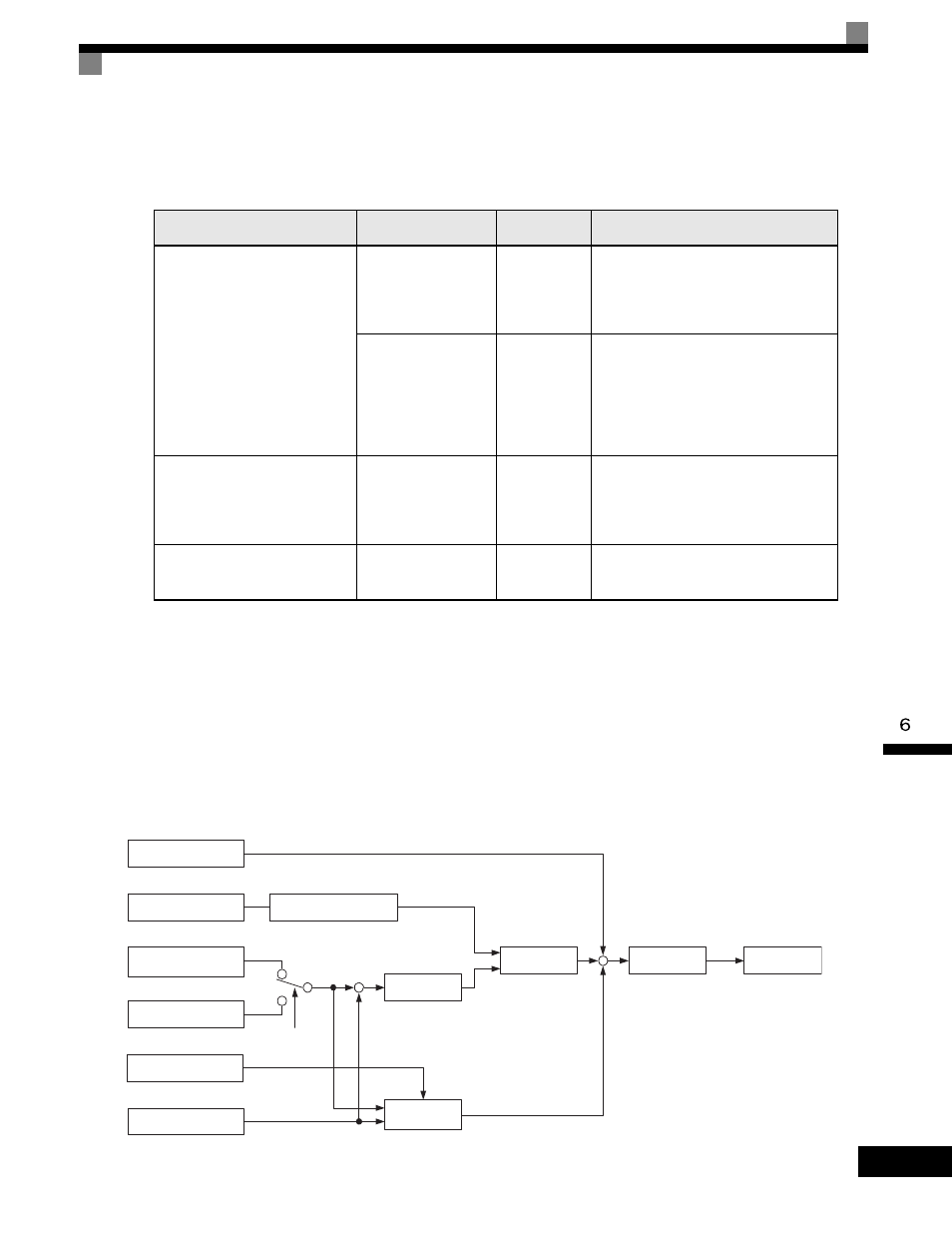
Fig 6.64 Torque Control Block Diagram
Torque Reference Input
Method
Reference Location
Selection
Method
Remarks
Voltage input (0 to
±
10 V)
Between A3 and AC
H3-04 = 1
H3-05 = 13
Set H3-04 to 0 for a 0 to 10-V torque ref-
erence.
To switch the torque reference between
positive and negative torque, set a multi-
function analog input to 78.
Between A2 and AC
(Turn OFF pin 2 of
SW1.)
H3-08 = 1
H3-09 = 13
Set H3-08 to 0 for a 0 to 10-V torque ref-
erence.
To switch the torque reference between
positive and negative torque, set a multi-
function analog input to 78.
The input can be used for torque compen-
sation by setting H3-09 to 14.
Current input (4 to 20mA)
Between A2 and AC
(Turn ON pin 2 of
SW1.)
H3-08 = 2
H3-09 = 13
To switch the torque reference between
positive and negative torque, set a multi-
function analog input to 78.
The input can be used for torque compen-
sation by setting H3-09 to 14.
Option Card (AI-14B)
(0 to
±
10 V)
Between TC2 and TC4
F2-01 = 0
H3-08 = 1
H3-09 = 13
The input can be used for torque compen-
sation by setting H3-05 to 14.
Torque reference
from analog input
Torque primary delay
filter
d5-02
Torque compensation
from analog input
Speed limit from analog
input from terminal A1
Speed limit
d5-04
1
2
d5-03
Speed limiter
Speed feedback
Speed limit bias
d5-05
+
Torque limit
Internal torque
reference
Refer to torque limit setting
via constants and analog input
Speed controller
(ASR)
Priority
circuit
+
+
+
−