Digital operator parameters: o – Yaskawa G7 Drive User Manual
Page 191
5
-80
Digital Operator Parameters: o
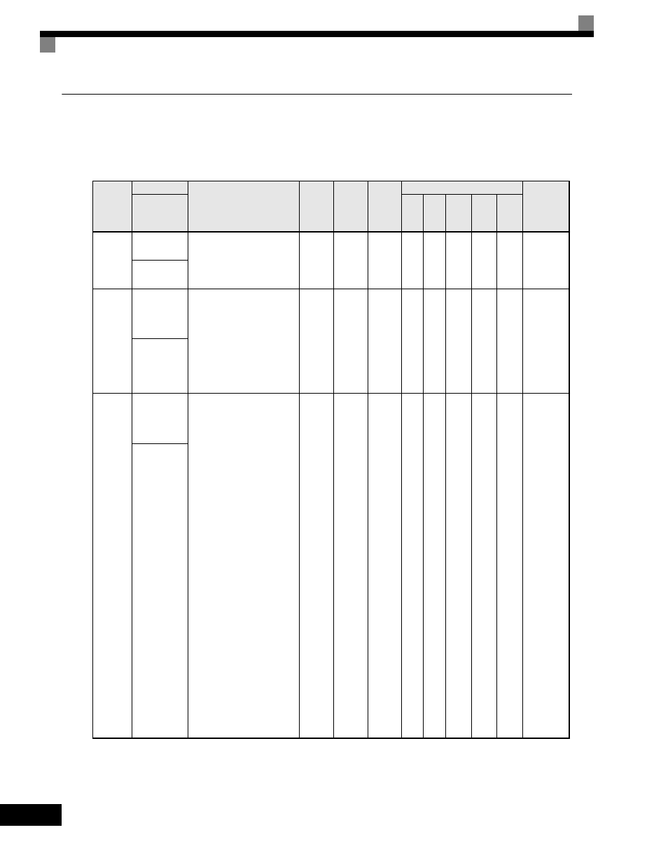
The following settings are made with the Digital Operator parameters (o parameters): Multi-function
selections and the copy function.Monitor Select: o1
User parameters for Digital Operator Displays are shown in the following table.
Parameter
Number
Name
Description
Setting
Range
Factory
Setting
Change
during
Operation
Control Methods
MODBUS
Register
Display
V/f
V/f
with
PG
Open
Loop
Vector
1
Flux
Vector
Open
Loop
Vector
2
o1-01
User Monitor
Selection
Selects which monitor will be
displayed in the operation
menu upon power-up when
o1-02 = 4.
4 to 48
6
Yes
A
A
A
A
A
500H
User Monitor
Sel
o1-02
User Monitor
Selection
After
Power-Up
Selects which monitor will
be displayed upon power-up.
1: Frequency Reference
(U1-01)
2: Output Frequency
(U1-02)
3: Output Current (U1-03)
4: User Monitor
(set by o1-01)
1 to 4
1
Yes
A
A
A
A
A
501H
Power-On
Monitor
o1-03
Digital
Operator
Display
Selection
Sets the units of the
Frequency References (d1-01
to d1-17), the Frequency
Reference Monitors
(U1-01, U1-02, U1-05), and
the Modbus communication
frequency reference.
0: Hz
1:
% (100% = E1-04)
2 RPM
(Enter
the
to
number of motor
39:
poles).
40 User
display.
to
Set the number
39999:desired at maximum
output frequency. 4
digit number. Number
of digits from the right
of the decimal point.
Example 1: o1-03 = 12000,
will result in frequency
reference from 0.0 to 200.0
(200.0 = Fmax).
Example 2: o1-03 = 21234,
will result in frequency
reference from 0.00 to 12.34
(12.34 = Fmax).
0
to
39999
0
No
A
A
A
A
A
502H
Display
Scaling