Installation orientation and space, Installation orientation and space -11 – Yaskawa G7 Drive User Manual
Page 24
Installation Orientation and Space
1-
11
Installation Orientation and Space
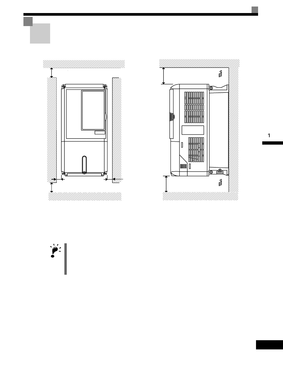
Install the Drive vertically so as not to reduce the cooling effect. When installing the Drive, always pro-
vide the following installation space to allow normal heat dissipation.
Fig 1.8 Drive Installation Orientation and Space
IMPORTANT
1. The same space is required horizontally and vertically for both Open Chassis (IP00) and Enclosed Wall-
mounted (IP20, NEMA 1 Type 1) Drives.
2. Always remove the protection covers before installing a 200-240 or 380-480 V Class Drive with an output
of 15 kW or less in a panel.
Always provide enough space for suspension eye bolts and the main circuit lines when installing a 200-240
or 380-480 V Class Drive with an output of 18.5 kW or more in a panel.
4.72in (120mm) minimum
4.75in (120mm) minimum
Air
Air
Vertical Clearance
Horizontal Clearance
1.2in
(30.5mm) minimum
1.2in
(30.5mm) minimum
1.97in (50mm) minimum
1.97in * (50mm) minimum
* For Drive model G7U4300, this clearance dimension is 11.81in (300mm) minimum. All other models require 1.97in (50mm) minimum.