Inputting master speed frequency reference only – Yaskawa G7 Drive User Manual
Page 220
Frequency Reference
6-
3
Inputting the Frequency Reference Using Voltage (Analog Setting)
When b1-01 is set to 1, you can input the frequency reference from control circuit terminal A1 (voltage input),
or control circuit terminal A2 (voltage or current input).
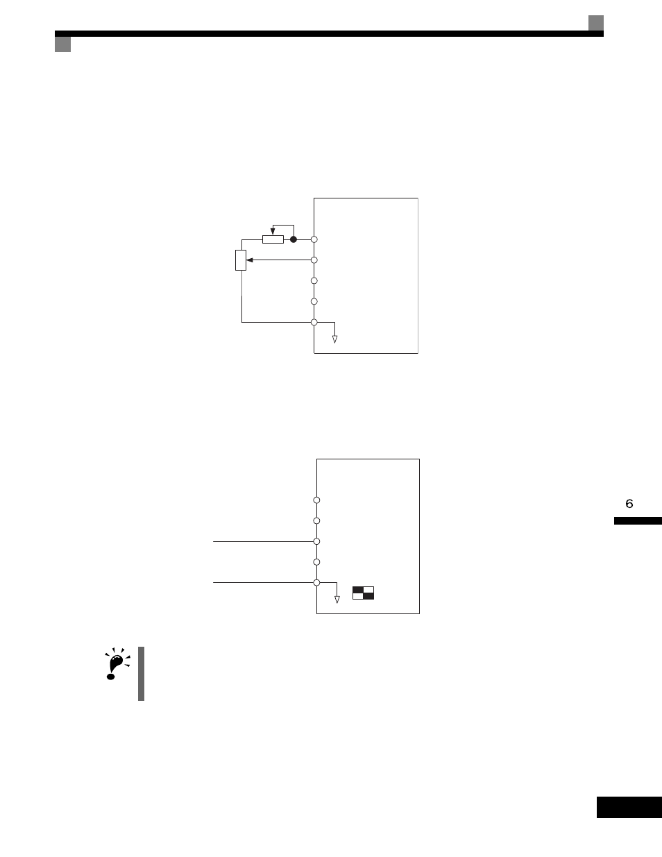
Inputting Master Speed Frequency Reference Only
When inputting a voltage for the master speed frequency reference, input the voltage to control circuit termi-
nal A1.
Fig 6.2 Voltage Input for Master Speed Frequency Reference
When inputting a current for the master speed frequency reference, input the current to control circuit terminal
A2, input 0Vto terminal A1, set H3-08 (Multi-function analog input terminal A2 signal level selection) to 2
(current input), and set H3-09 (Multi-function analog input terminal A2 function selection) to 0 (add to termi-
nal A1).
Fig 6.3 Current Input for Master Speed Frequency Reference
IMPORTANT
Turn ON pin 2 of DIP switch SW1 (toward I), the voltage/current switch, when inputting a current to terminal
A2. Turn OFF pin 2 of DIP switch SW1 (toward V), the voltage/current switch, when inputting a voltage to ter-
minal A2. Set H3-08 to the correct setting for the type of input signal being used.
Inverter
A1
A2
A3
Master speed frequency
reference
(voltage input)
Master speed frequency
reference
(current input)
Auxiliary speed frequency
reference 1
AC Analog common
2 k
Ω
+V Power supply: 15 V,
20 mA
Inverter
A1
A2
A3
Master speed frequency
reference
(voltage input)
Master speed frequency
reference
(current input)
Auxiliary speed frequency
reference 1
AC Analog common
+V
4 to 20-mA input
DIP switch
S1
I
V
1
2
Power supply: 15 V,
20 mA