Control circuit terminal connections, Wiring control circuit terminals, Fig 2.16 control circuit terminal connections – Yaskawa G7 Drive User Manual
Page 60
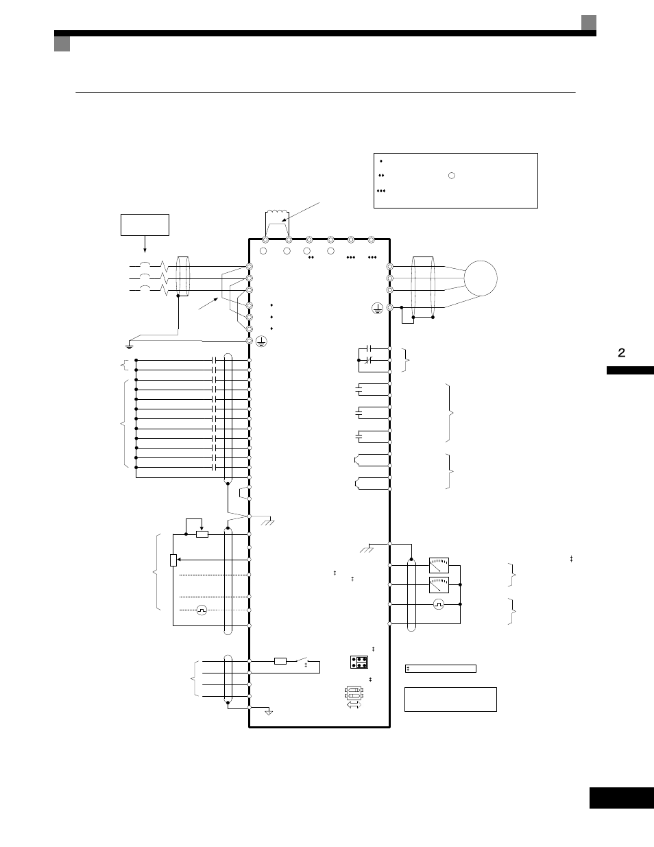
Wiring Control Circuit Terminals
2-
29
Control Circuit Terminal Connections
Connections to Drive control circuit terminals are shown in Fig 2.16.
Fig 2.16 Control Circuit Terminal Connections
T/L3
S/L2
R/L1
S3
(H1-01)
S2
S1
SC
E(G)
S4
(H1-02)
S5
(H1-03)
S6
(H1-04)
S7
(H1-05)
SN
S+
R-
R+
S-
IG
G7
W/T3
V/T2
U/T1
MC
MB
MA
M2
M1
M4
M3
E(G)
(H4-01) FM
(H4-04) AM
AC
(H2-01)
(H2-02)
Modbus RTU
Communications
RS-485/422
19.2 Kbps
External
Frequency
Reference
MCCB
L3
L2
L1
3-Phase
Power Supply
50/60Hz
Reverse Run/Stop
Foward Run/Stop
Multi-function
Digital Inputs
24VDC, 8mA
M
Motor
Digital Output 1
Fault Contact
250VAC, 30VDC, 1A
Multi-function
Digital Outputs 2-4
250VAC, 30VDC, 1A
+
-
+
-
Terminating
Resistor
S8
(H1-06)
M6
M5
(H2-03)
Digital Inputs
24VDC, 8mA
SP +24VDC
+V +15VDC +/-10%, 20mA
AC
2k
Ω
RP 0 to 32kHz, 5 to 12VDC, 3k ***
Multi-function Pulse Input
(H6-01)
S1-1
-V -15VDC +/-10%, 20mA
Ω
(H6-06) MP
S9
(H1-07)
S10
(H1-08)
S11
(H1-09)
S12
(H1-10)
C3
P3
(H2-04)
P4
(H2-05)
C4
Multi-function
Digital Outputs 5-6
48VDC, 50mA
+ 1
+ 2
+ 3
-
Shorting Bar Standard:
CIMR-G7U20P4 to 2015
CIMR-G7U40P4 to 4015
DC Link Choke
Standard:
CIMR-G7U2018 to 2110
CIMR-G7U4018 to 4300
U
X
Remove if adding
external DC link
choke
B1
B2
Jumper CN15
V
CH1
CH2
DIP Switch S1
S1-1
OFF
ON
S1-2
T/L31
S/L21
R/L11
Remove jumpers if
using 12 pulse input
2k
Ω
Ω
A3 0 to +/-10VDC, 20k *
Multi-function Analog Input 2
(H3-05)
A1 0 to +/-10VDC, 20 k *
Ω
110
Ω
* +/-11 Bit Resolution, 0.2% Accuracy
** 10 Bit Resolution, 0.2% Accuracy
*** +/-1% Accuracy
See Page 2-25 for details.
A2 4 to 20mA, 250 *
[0 to +/-10VDC, 20k **]
Multi-function Analog Input 1
(H3-09)
Ω
Ω
(S1-2 ON)
(S1-2 OFF)
Output Frequency
T1
T2
T3
Branch circuit
protection supplied
by others.
Fault Reset
External Fault
Multi-Step Reference2
Multi-Step Reference1
Baseblock
Jog Reference
Fast-Stop N.O.
Accel / Decel Time 1
Multi-Step Reference4
Multi-Step Reference3
During Run
Zero Speed
Frequency Agree 1
Inverter Ready
Minor Fault - Alarm
Output Current
Multi-function Analog
Output 1 - 2
0 to +/-10VDC, 2mA
4-20mA, 500
+/-9 Bit Resolution
+/- 8% Accuracy
Ω
Output Frequency
Multi-function
Pulse Output
0 to 32kHz
9VDC @ 3k
+/-1% Accuracy
Ω
+
12 Pulse Input Terminals R1/L11, S1/L21, T1/L31 are standard
on CIMR-G7U2018 - 2110 and CIMR-G7U4018 - 4300.
External Braking Terminal 3 is standard on CIMR-G7U2018 -
2110 and CIMR-G7U4018 - 4300.
Braking Terminals B1, B2 are standard on CIMR-G7U20P4 -
2015 and CIMR-G7U40P4- 4015.