Control circuit wire sizes, Wiring checks, Control circuit wiring precautions – Yaskawa G7 Drive User Manual
Page 61
2
-30
Control Circuit Wiring Precautions
Observe the following precautions when wiring control circuits.
•
Separate control circuit wiring from main circuit wiring (terminals R/L1, S/L2, T/L3, B1, B2, U/T1, V/T2,
W/T3, , 1, 2,
and 3)
and
other
high-power
lines.
•
Separate wiring for control circuit terminals MA, MB, MC, M1, M2, M3, M4, M5, and M6 (contact
outputs) from wiring to other control circuit terminals.
•
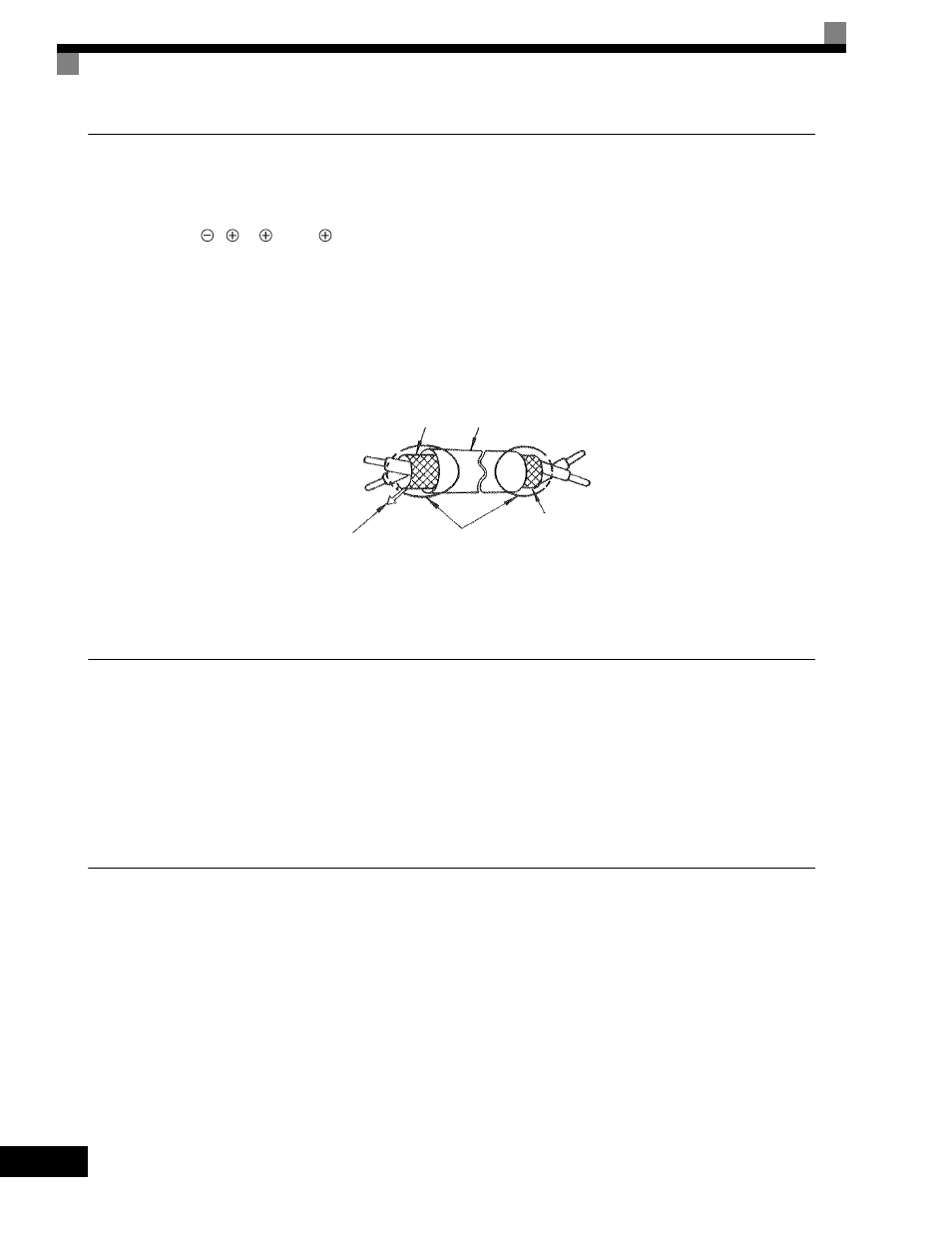
Use twisted-pair or shielded twisted-pair cables for control circuits to prevent operating faults. Process
cable ends as shown in Fig 2.17.
•
Connect the shield wire to terminal E (G).
•
Insulate the shield with tape to prevent contact with other signal lines and equipment.
Fig 2.17 Processing the Ends of Twisted-pair Cables
Control Circuit Wire Sizes
For remote operation, keep the length of the control wiring to 50m or less. Separate the control wiring from high-
power lines (input power, motor leads or relay sequence circuits) to reduce noise induction from peripheral devices.
When setting speed commands from an external speed potentiometer, use shielded twisted-pair wires and ground the
shield to terminal E(G), as shown above. Terminal numbers and wire sizes are shown in Table 2.9.
Wiring Checks
Check all wiring after wiring has been completed. Do not perform a buzzer check on control circuits. Perform
the following checks on the wiring.
•
Is all wiring correct?
•
Have any wire clippings, screws, or other foreign material been left?
•
Are all screws tight?
•
Are any wire ends contacting other terminals?
Shield sheath
Armor
Connect to shield sheath
terminal at Drive
(terminal E (G))
Insulate with tape
Do not connect here.