1 procedure – Yaskawa G5HHP Drive User Manual
Page 107
5.1 Procedure
5 - 3
5.1 Procedure
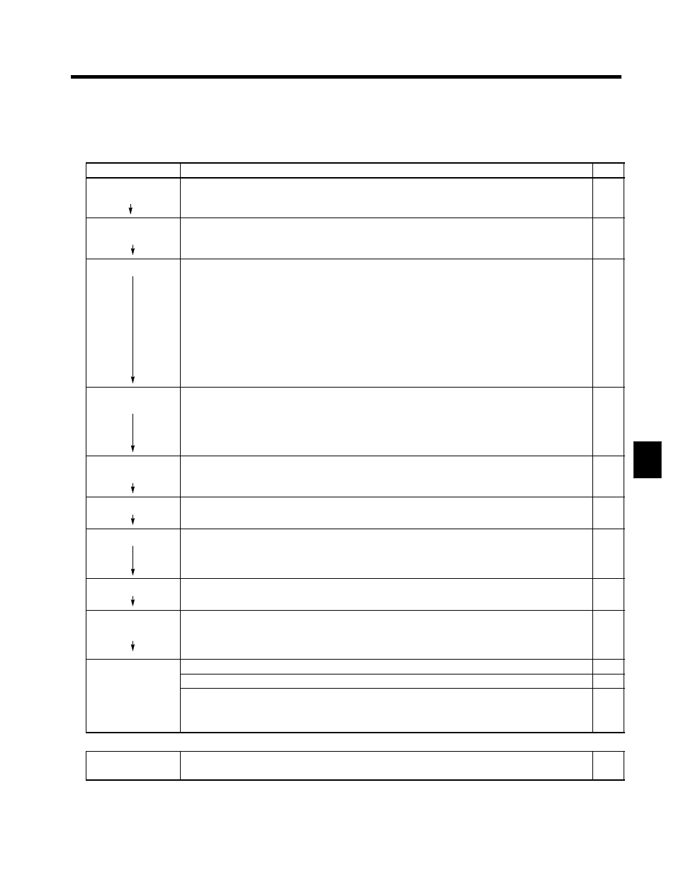
Perform trial operation according to the following operational flow.
Item
Contents
Page
Installation and
Mounting
Install the Inverter according to the installation conditions.
2 - 1
S
Ensure that the installation conditions are met.
Wiring and
Connection
Connect to the power supply and peripheral devices.
3 - 1
S
Select peripheral devices which meet the specifications and wire correctly.
Power ON
Carrying out the following pre-connection checks before turning ON the power supply:
5 - 4
S
Always ensure that a power supply of the correct voltage is used and that the power input terminals (R, S, T) are
wired correctly.
400-V class: 3-phase 380 to 460 VAC, 50/60 Hz
575-V class: 3-phase 500 to 600 VAC, 50/60 Hz
S
Make sure that the Motor output terminals (U, V, W) and the Motor are connected correctly.
S
Make sure that the control circuit terminals and the control device are wired correctly. Make sure that all control
circuit terminals are turned OFF.
S
When using a PG Speed Control Card, ensure that it is wired correctly.
S
Set the motor to no-load status, (not connected to the mechanical system).
Having conducted the above checks, connect the power supply.
Check the Display
Status
Check to be sure that there are no faults in the Inverter.
5 - 4
*1
S
If the display at the time the power is connected is normal, it will read as follows:
Data Display: Frequency Ref
S
When an fault has occurred, the details of the fault will be displayed. In that case, refer to Section 9 Maintenance
Operations.
Setting the Input
Voltage
Set the Inverter input voltage (E1-01) to the correct voltage.
5 - 5
Set the Motor
Set the proper motor protection (E1-02).
5 - 10
Autotuning
Execute autotuning in the open-loop vector control mode.
5 - 10
*2
S
When autotuning is executed, motor constants are set automatically.
S
When motor constants cannot be set using autotuning, input each constant for the motor.
No-load Operation
Start the no-load motor using the Digital Operator.
5 - 12
S
Set the frequency reference using the Digital Operator and start the motor using key sequences.
Actual Load
Operation
Connect the mechanical system and operate using the Digital Operator.
5 - 12
S
When there are no difficulties using the no-load operation, connect the mechanical systemto themotorandoperate
using the Digital Operator.
Operation
Basic Operation: Operation based on the basic settings required to start and stop the Inverter.
6 - 1
Advanced Operation: Operation which uses PID control or other functions.
7 - 1
S
For operation within standard constants select “Basic Operation.”
S
To use the various applied functions such as, direct current control braking, speed search, timer, S-curve accelera-
tion/deceleration, slip compensation, torque compensation, droop control, zero-servo, and torque control, select
“Advanced Operation” in combination with “Basic Operation.”
----
* It is sometimes necessary to initialize constants after checking the display status.
Initializing Constants
Initialize the constants.
5 - 4
S
Check the Inverter capacity setting (kVA) in o2-04 before replacing the controller PCB with a spare.
*2 When motor cannot be disconnected from the load, motorconstants can be set by calculations. Contact your Yaskawa representa-
tives for details.
5