Yaskawa G5HHP Drive User Manual
Page 259
7.5 Common Functions
7 - 95
S
The Inverter might be damaged when using the fault restart function too frequently.
S
Understanding that the Inverter might be damaged, be sure to take the following precautions:
Always set up a molded-case circuit breaker (MCCB).
Set up a sequence that will stop peripheral equipment when an Inverter fault occurs.
D
The fault restart function automatically restarts the Inverter even when an internal fault occurs during
Inverter operation. Use this function only when continuing operation is more important than possibly
damaging the Inverter.
D
The fault restart function is effective with the following faults. With other faults, the protective opera-
tions will engage immediately without attempting to restart operation.
S
OC (Overcurrent)
S
PF (Main circuit voltage fault)
S
OL1 (Motor overload)
S
GF (Ground fault)
S
LF (Output open-phase)
S
OL2 (Inverter overload)
S
PUF (Fuse blown)
S
RF (Braking resistor overheated)
S
OL3 (Overtorque)
S
OV (Main circuit overvoltage)
S
RR (Braking transistor fault)
S
OL4 (Overtorque)
S
UV1 (Main circuit undervoltage)
D
The fault restart count is cleared in the following cases:
•
When operation is normal for 10 minutes after a fault restart is performed.
•
When the fault reset input is received after the protection operation has been activated and the fault
confirmed.
•
When the power is turned OFF and then ON again.
D
When one of the multi-function outputs (H2-01, H2-02, or H2-03) is set to 1E (Restart Enabled), the
output will be ON while the fault restart function is in progress.
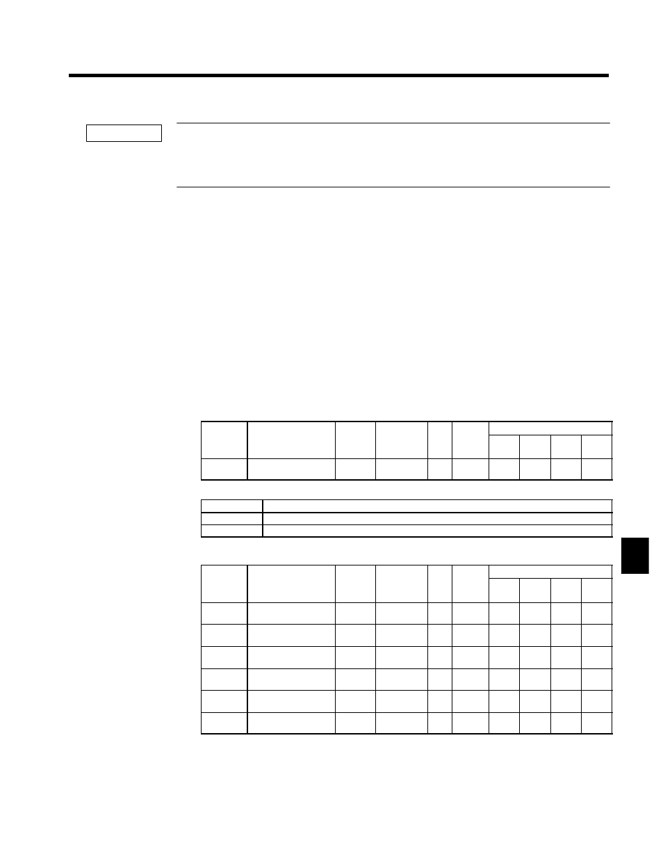
Auto Restart Operation Selection: L5-02
User
Change
during
Setting
Factory
Valid Access Levels
User
Constant
Number
Name
g
during
Opera-
tion
Setting
Range
Unit Factory
Setting
V/f
Control
V/f with
PG
Open
Loop
Vector
Flux
Vector
L5-02
Auto restart operation
selection
x
0, 1
--
0
B
B
B
B
D
Settings
Setting
Function
0
Do not output fault restart. (The fault contact does not operate.)
1
Output fault restart. (The fault contact operates.)
J
Overtorque Detection Settings: L6-01 to L6-06
User
Change
during
Setting
Factory
Valid Access Levels
User
Constant
Number
Name
g
during
Opera-
tion
Setting
Range
Unit Factory
Setting
V/f
Control
V/f with
PG
Open
Loop
Vector
Flux
Vector
L6-01
Torque detection
selection 1
x
0 to 4
--
0
B
B
B
B
L6-02
Torque detection level
1
x
0 to 300
%
150
B
B
B
B
L6-03
Torque detection time
1
x
0.0 to 10.0
s
0.1
B
B
B
B
L6-04
Torque detection
selection 2
x
0 to 4
--
0
A
A
A
A
L6-05
Torque detection level
2
x
0 to 300
%
150
A
A
A
A
L6-06
Torque detection time
2
x
0.0 to 10.0
s
0.1
A
A
A
A
D
The overtorque detection function detects an excessive mechanical load from an increase in the output
current (or output torque).
D
The settings in the torque detection selection constants (L6-01 and L6-04) determine whether overtor-
que conditions will be detected and what kind of processing will be performed if a overtorque condition
is detected.
7
IMPORTANT