Yaskawa G5HHP Drive User Manual
Page 224
Advanced Operation
7.5.4 Option Constants: F
7 - 60
J
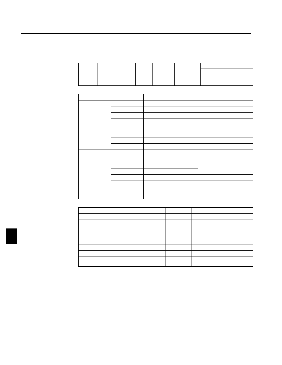
DO-08 Digital Output Card Settings: F6-01
D
Set the output mode in the following constants when using a DO-08 Digital Output Card.
User
Change
during
Setting
Factory
Valid Access Levels
User
Constant
Number
Name
g
during
Opera-
tion
Setting
Range
Unit Factory
Setting
V/f
Control
V/f with
PG
Open
Loop
Vector
Flux
Vector
F6-01
Output mode selection
x
0, 1
--
0
B
B
B
B
D
The items output from the DO-08 will be as follows according to the setting of F6-01.
Setting
Terminal
Output
TD5-TD11
Overcurrent (SC, OC, GF)
TD6-TD11
Overvoltage (OV)
TD7-TD11
Inverter overload (OL2)
0: 8 channels of
individual out
TD8-TD11
Fuse blown (PUF)
individual out-
puts
TD9-TD11
Overspeed (OS)
puts
TD10-TD11
Inverter overheat (OH1) or motor overload (OL1)
TD1-TD2
Zero speed detection
TD3-TD4
Speed agree
TD5-TD11
Bit 0
TD6-TD11
Bit 1
Binary code (see below)
TD7-TD11
Bit 2
Binary code (see below)
1: Binary code
TD8-TD11
Bit 3
1: Binary code
output
TD9-TD11
Zero speed detection
TD10-TD11
Speed agree
TD1-TD2
Running
TD3-TD4
Minor fault
Coded Outputs
Bit 3210
Meaning
Bit 3210
Meaning
0000
No fault
1000
External fault (EF x x)
0001
Overcurrent (SC, OC, GF)
1001
Controller fault (CPFx x)
0010
Overvoltage (OV)
1010
Motor overload (OL1)
0011
Inverter overload (OL2)
1011
Not used
0100
Inverter overheat (OH, OH1)
1100
Power loss (UV1. UV2, UV3)
0101
Overspeed (OS)
1101
Excessive speed deviation (DEV)
0110
Fuse blown(PUF)
1110
PG disconnected (PGO)
0111
Braking Resistor Unit overheat (RH)
Braking Transistor fault (RR)
1111
Not used.
7