Frequency reference selection: b1-01 – Yaskawa G5HHP Drive User Manual
Page 122
Basic Operation
6.1.2 Frequency Reference Settings: b1-01, H3-01, H3-08, H3-09
6 - 4
6.1.2 Frequency Reference Settings: b1-01, H3-01, H3-08, H3-09
These settings are required when inputting analog voltage or current signals from the control circuit terminals.
J
Frequency Reference Selection: b1-01
D
Constant b1-01 is used to select the reference source.
User
Change
during
Setting
Factory
Valid Access Levels
User
Constant
Number
Name
g
during
Opera-
tion
Setting
Range
Unit Factory
Setting
V/f
Control
V/f with
PG
Open
Loop
Vector
Flux
Vector
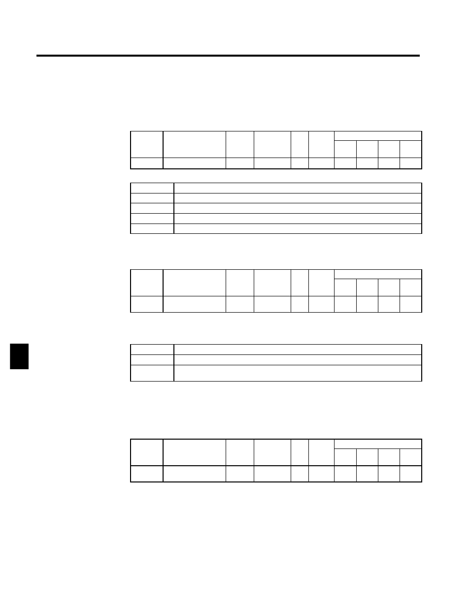
b1-01
Reference selection
x
0 to 3
--
1
Q
Q
Q
Q
D
Settings
Setting
Reference source
0
Digital Operator
1
Control circuit terminals (analog inputs)
2
Transmission
3
Optional Card
D
The frequency reference is input from the control circuit terminals (external terminals), so set b1-01 to
1.
J
Frequency Reference (Voltage), Terminal 36 Signal Level: H3-01
User
Change
during
Setting
Factory
Valid Access Levels
User
Constant
Number
Name
g
during
Opera-
tion
Setting
Range
Unit Factory
Setting
V/f
Control
V/f with
PG
Open
Loop
Vector
Flux
Vector
H3-01
Signal level selection
(terminal 36)
x
0, 1
--
0
B
B
B
B
D
The frequency reference (voltage) is valid when constant b1-01 has been set to 1.
D
Set the voltage range for the frequency reference (voltage) signal.
D
Settings
Setting
Function
0
0 to 10 VDC input [11--bit + polarity (positive/negative) input]
1
--10 to 10 VDC input
(A negative voltage is a reference for reverse rotation.)
J
Frequency Reference (Current), Terminal 39 Signal Level: H3-09, H3-08
D
Set terminal 39 to a frequency reference with constant H3-09 to use terminal 39 as the frequency refer-
ence terminal.
D
The frequency reference setting is 1F.
Function Selection: H3-09
User
Change
during
Setting
Factory
Valid Access Levels
User
Constant
Number
Name
g
during
Opera-
tion
Setting
Range
Unit Factory
Setting
V/f
Control
V/f with
PG
Open
Loop
Vector
Flux
Vector
H3-09
Multi-function analog
input (terminal 39)
x
1 to 1F
--
1F
A
A
A
A
D
After setting constant H3-09, set terminal 39 signal level with H3-08.
Signal Level: H3-08
D
The frequency reference (current) is valid when constant b1-01 has been set to 1.
D
Set the signal level for the frequency reference (current).
6