Yaskawa G5HHP Drive User Manual
Page 195
7.3 Flux Vector Control
7 - 31
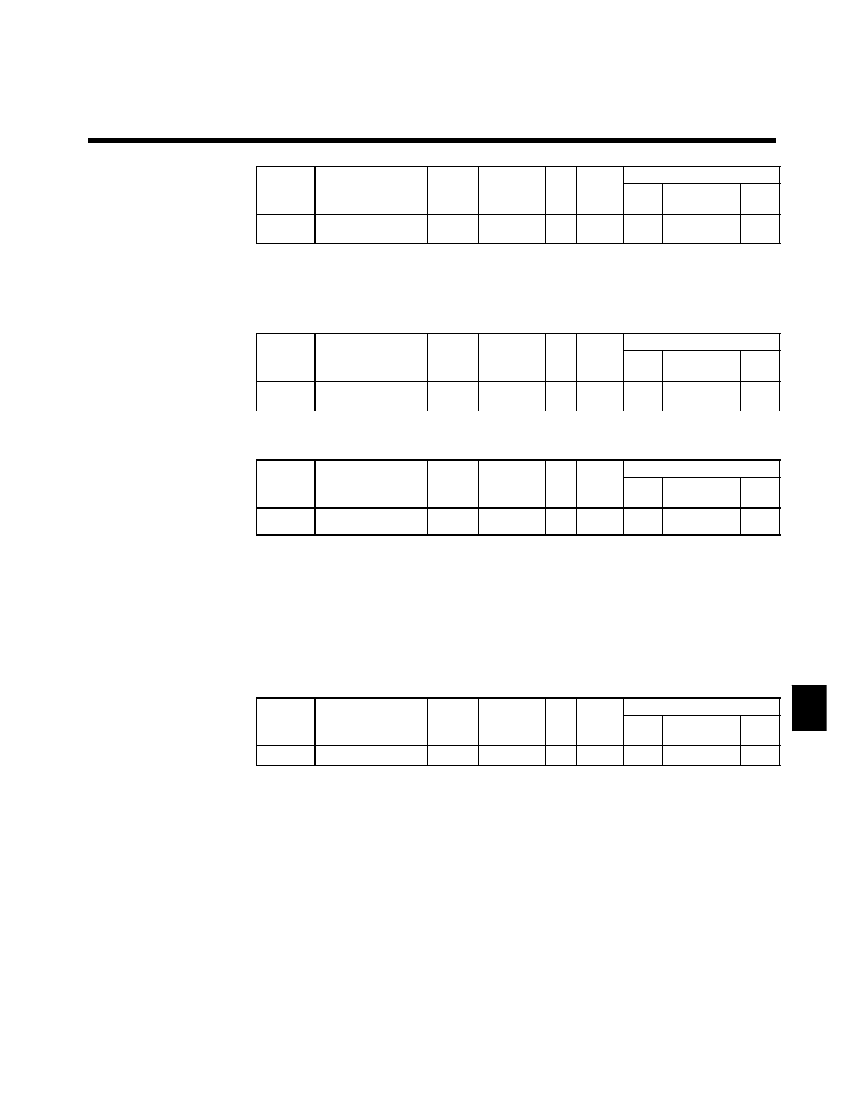
Motor No-load Current: E2-03
User
Change
during
Setting
Factory
Valid Access Levels
User
Constant
Number
Name
g
during
Opera-
tion
Setting
Range
Unit Factory
Setting
V/f
Control
V/f with
PG
Open
Loop
Vector
Flux
Vector
E2-03
Motor no-load current
x
0.00 to
2000.0
A
96.0
A
A
Q
Q
D
The default setting depends upon the Inverter capacity.
(The table shows the default settings for 400-V class, 200 kW Inverters.) (See page 8 - 42.)
D
Set the no-load current (E2-03) at the rated voltage and rated frequency. Normally this value isn’t shown
on the motor nameplate, so it might be necessary to contact the motor manufacturer.
Number of Motor Poles: E2-04
User
Change
during
Setting
Factory
Valid Access Levels
User
Constant
Number
Name
g
during
Opera-
tion
Setting
Range
Unit Factory
Setting
V/f
Control
V/f with
PG
Open
Loop
Vector
Flux
Vector
E2-04
Number of motor
poles
x
2 to 48
--
4
x
Q
x
Q
D
Set the number of poles (E2-04) shown on the motor nameplate.
Motor Line-to-line Resistance: E2-05
User
Change
during
Setting
Factory
Valid Access Levels
User
Constant
Number
Name
g
during
Opera-
tion
Setting
Range
Unit Factory
Setting
V/f
Control
V/f with
PG
Open
Loop
Vector
Flux
Vector
E2-05
Motor line-to-line re-
sistance
x
0.000 to
65.000
Ω
0.020
A
A
A
A
D
The default setting depends upon the Inverter capacity.
(The table shows the default settings for 400-V class, 200 kW Inverters.) (See page 8 - 42.)
D
Set the motor terminal resistance (U--V, V--W, and W--U) in constant E2-05.
D
Normally this value isn’t shown on the motor nameplate, so it might be necessary to contact the motor
manufacturer for the terminal resistance at the insulation class temperature. Use the following equations
to calculate the resistance value from the terminal resistance of a test report.
•
E-class insulation: Terminal resistance at 75°C in the test report (Ω) x 0.92
•
B-class insulation: Terminal resistance at 75°C in the test report (Ω) x 0.92
•
F-class insulation: Terminal resistance at 115°C in the test report (Ω) x 0.87
Motor Leak Inductance: E2-06
User
Change
during
Setting
Factory
Valid Access Levels
User
Constant
Number
Name
g
during
Opera-
tion
Setting
Range
Unit Factory
Setting
V/f
Control
V/f with
PG
Open
Loop
Vector
Flux
Vector
E2-06
Motor leak inductance
x
0.0 to 30.0
%
5.0
x
x
A
A
D
The default setting depends upon the Inverter capacity.
(The table shows the default settings for 400-V class, 200 kW Inverters.) (See page 8 - 42.)
D
Set the voltage drop (caused by the motor’s leakage inductance) as a percentage of the motor’s rated
voltage in constant E2-06.
D
This constant does not normally require setting because the Inverter automatically compensates during
operation.
D
Normally this value isn’t shown on the motor nameplate, so it might be necessary to contact the motor
manufacturer. It is also acceptable to set the loss (caused by the motor’s leakage inductance) as a percent-
age.
7