4 wiring examples, 1 using two braking units in parallel – Yaskawa G5HHP Drive User Manual
Page 353
12.4 Wiring Examples
12 - 5
12.4 Wiring Examples
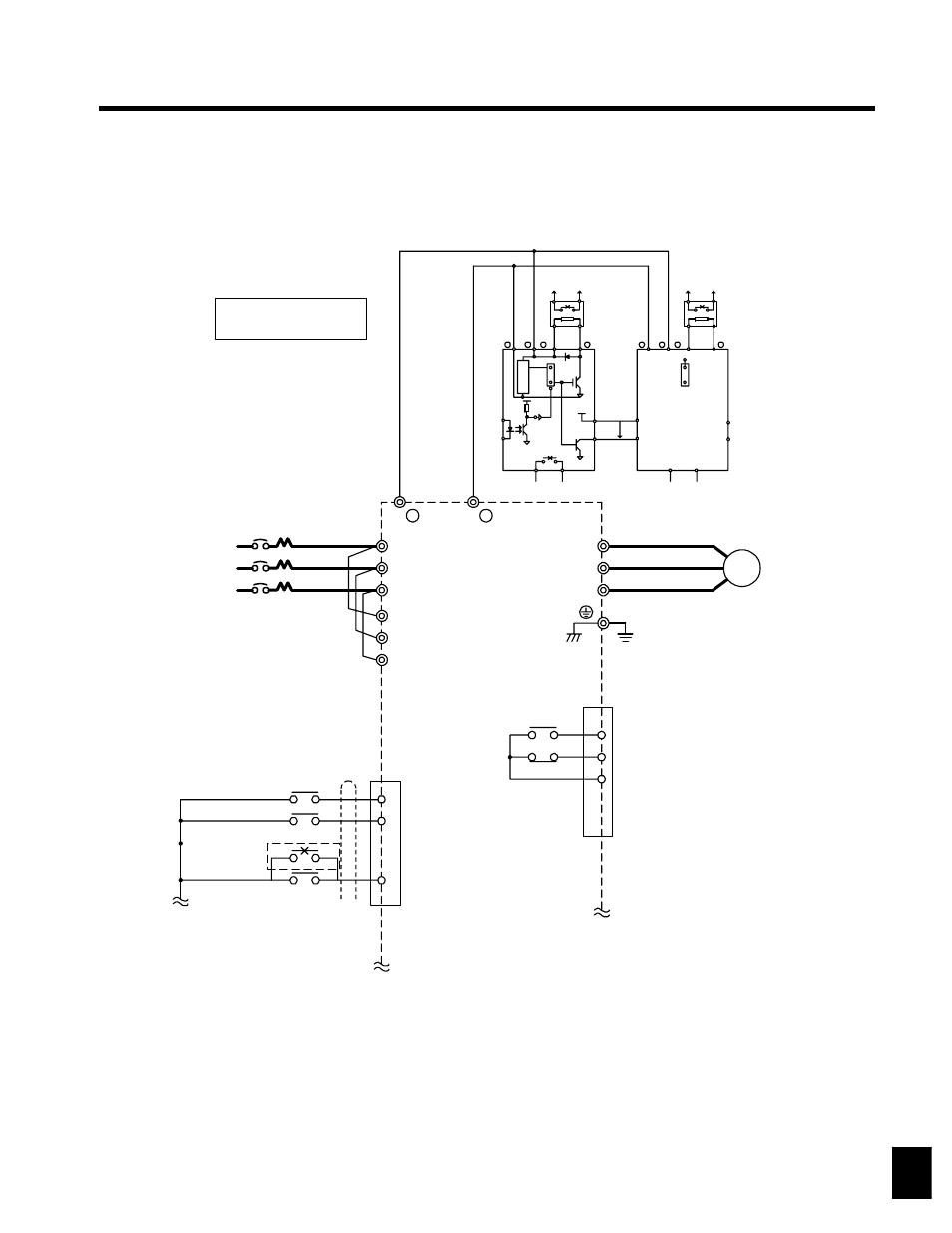
12.4.1 Using Two Braking Units in Parallel
Braking Unit 2
MCCB
3-phase power
380 to 460 V
50/60 Hz
500 to 600 V
50/60 Hz
Braking Unit
(Ground to 100 Ω max.)
Thermal protector
Braking
Resis-
tor Unit
Thermal switch
Thermal switch
Level
MASTER
SLAVE
A sequence is required to turn
OFF the power supply for the
thermal overload relay trip con-
tacts of the Braking Resistor Unit.
* Disable stall prevention during deceleration by setting L3-04 to “0” when using a Braking
Resistor Unit. The motor may not stop within the deceleration time if this setting is not
changed.
Thermal protector
Braking
Resis-
tor Unit
MASTER
SLAVE
Forward Run/Stop
Forward run command
(forward run when closed)
Reverse Run/Stop
Reverse run command
(reverse run when closed)
External fault
External contact
output (1 A max.
at 30 VDC)
3CN
23
8
14
IM
U/T1
V/T2
W/T3
+
--
R
S
T
1
13
25
3CN
6
3
4
T/L3
S/L2
R/L1
T1/L31
S1/L21
R1/L11
1
2
3
4
6
5
+15
--
+
--
+
0
0
B
P
1
2
--
+
--
+
P
VS--616G5
1
2
B
P
0
0
1
2
6
5
3
4
Motor
12