8 grounding, 1 connection of ground bus bar, 2 connection of ground cable for control signals – Yaskawa G5HHP Drive User Manual
Page 67
3.8 Grounding
3 - 27
3.8 Grounding
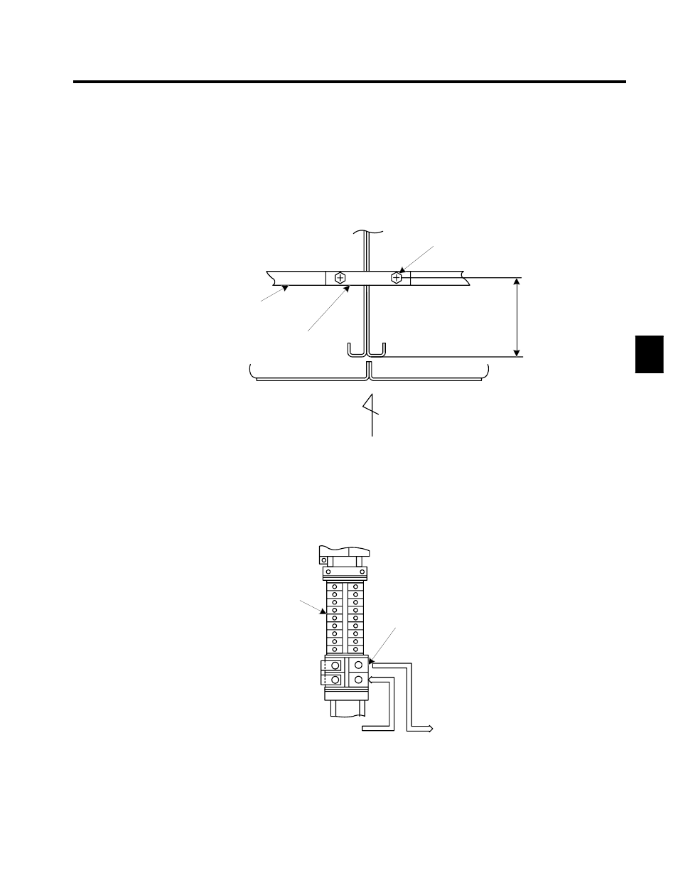
3.8.1 Connection of Ground Bus Bar
When connecting the Inverter Panel side-by-side with an I/O terminal panel or general panel, firmly secure
the bus bar connector or cable between the ground bus bars with bolts as shown in Figure 3.21.
To avoid any troubles or accidents that might be caused by a rise in voltage to ground due to current leakage,
make sure that the bus bar is grounded before applying power.
Tightening bolt
(M8 20 mm)
Ground
bus bar
Ground bus bar
connector
415
Fig 3.21
Ground Bus Bar Connection for 400-V (600 kW) Inverters Connected
Side-by-side
3.8.2 Connection of Ground Cable for Control Signals
Separate the ground cable for control signals from the ground bus bar and apply a class-3 ground (100 Ω
or less).
2TB
(General
terminal
block)
ES terminals (two)
UKT--81
Terminal bolts: M5
Connecting wire: 14 mm
2
Ground cable
Fig 3.22
Connection of Ground Cable for Control Signals
3