Yaskawa G5HHP Drive User Manual
Page 163
6.5 V/f Control with PG
6 - 45
Constant
Explanation
Setting
H4-04 Analog output selection (terminal 48)
5
Settings that allow multi-function
H4-05 Analog output gain (terminal 48)
1.00
Settings that allow multi-function
analog output 2 to be used to moni-
t th
t
d
H4-06 Analog output bias (terminal 48)
0.0
g
p
tor the motor speed.
H4-07Analog output level selection
1
This setting allows a 0 to ±10 V sig-
nal range to be monitored.
The multi-function analog outputs have the following functions with these constant settings.
•
Multi-function analog output 1 (terminal 45): Outputs Inverter’s output frequency(0 to ±10 V).
•
Multi-function analog output 2 (terminal 48): Outputs the actual motor speed (0 to ±10 V).
Terminal 46 is the multi-function analog output common.
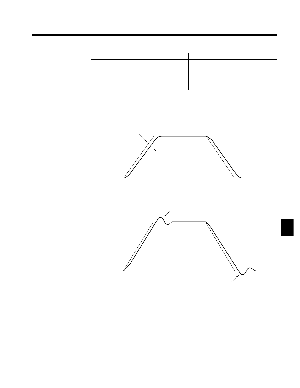
We recommend monitoring both the output frequency and the motor speed to monitor the response delay
or deviations from the reference value, as shown in the following diagram.
Motor speed
Output frequency
Time
Motor speed (response)
Fig 6.23
Example Monitor Waveforms
3. Give acceleration/deceleration commands and adjust the gain while observing the waveform.
Motor speed
Time
If overshooting occurs:
Decrease C5-01 and increase C5-02.
If undershooting occurs:
Decrease C5-03 and increase C5-04.
Fig 6.24
Gain Adjustments
6