Yaskawa G5HHP Drive User Manual
Page 252
Advanced Operation
7.5.6 Protective Functions: L
7 - 88
D
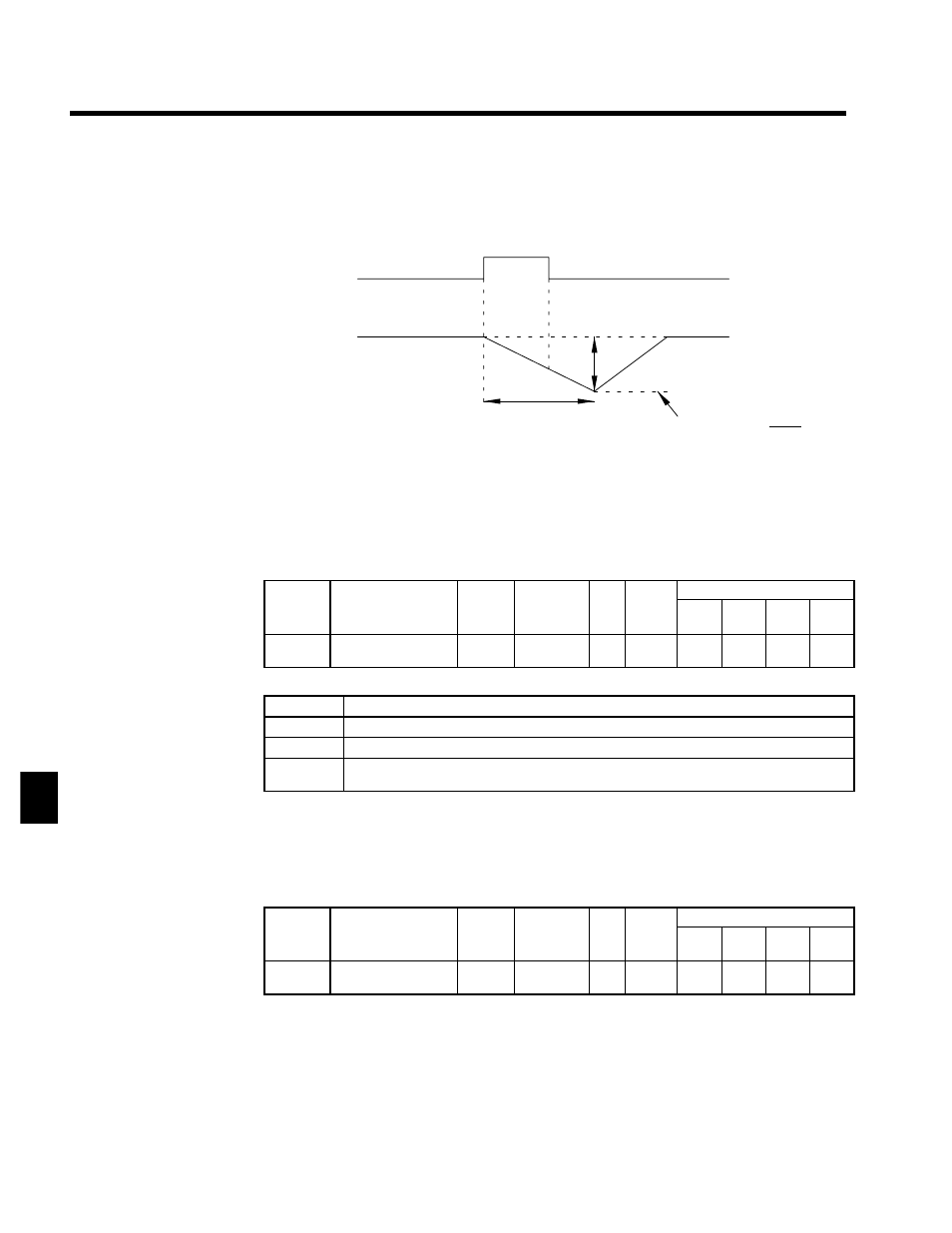
L2-06
≠ 0
The motor is decelerated to the KEB frequency level using the momentary power loss ridethru time
(L2-02) and then is accelerated to the original frequency reference using acceleration time 1 (C1-01).
The KEB frequency level is calculated from the KEB frequency rate using the following equation.
KEB frequency level = Output frequency before power loss [1 -- (setting of L2-06)/100)]%
Multi-function input
terminal setting
(H1
-
01 to 06 = 65 or 66)
OFF
ON
Momentary power loss ride-
thru time (L2-02)
L2
-
06
C1
-
01
OFF
Output frequency
Output frequency (1 -- L2-06
100%)
J
Stall Prevention Function Settings: L3-01 to L3-06
D
A stall occurs if the rotor cannot keep up with the rotating magnetic field on the motor stator side when
a large load is applied to the motor or a sudden acceleration/deceleration is performed.
D
In the Inverter, stall prevention functions can be set independently for accelerating, running, and decel-
erating. (Some functions are restricted depending on the control method.)
Stall Prevention Selection During Acceleration: L3-01
User
Change
during
Setting
Factory
Valid Access Levels
User
Constant
Number
Name
g
during
Opera-
tion
Setting
Range
Unit Factory
Setting
V/f
Control
V/f with
PG
Open
Loop
Vector
Flux
Vector
L3-01
Stall prevention selec-
tion during accel
x
0 to 2
--
1
B
B
B
x
D
Settings
Setting
Function
0
Disabled. (Accelerate according to the settings. Stalls may occur with large loads.)
1
Enabled. (Stop acceleration if L3-02 setting is exceeded. Accelerate again when current recovers.)
2
Optimum acceleration (Adjust acceleration so that the L3-02 isn’t exceeded by much. Disregard
the acceleration time setting.)
D
When setting 1 (enabled) is selected, acceleration is stopped if the motor current exceeds the accelera-
tion stall prevention level. Acceleration is started again when the current falls below this level. The ac-
celeration time can be longer than the setting depending on the load.
D
When setting 2 (optimum acceleration) is selected, acceleration is performed using the acceleration stall
prevention level as a basis. In this case, the acceleration time is disregarded.
Stall Prevention Level During Acceleration: L3-02
User
Change
during
Setting
Factory
Valid Access Levels
User
Constant
Number
Name
g
during
Opera-
tion
Setting
Range
Unit Factory
Setting
V/f
Control
V/f with
PG
Open
Loop
Vector
Flux
Vector
L3-02
Stall prevention level
during accel
x
0 to 200
%
150
B
B
B
x
D
This setting is valid when L3-01 is set to 1 or 2.
D
Normally it isn’t necessary to change this setting.
D
Decrease this setting when the motor capacity is small compared to the Inverter capacity or stalling oc-
curs when the motor is operated with the factory setting. The standard target setting is 2 to 3 times the
motor’s rated current. (Set this current value as a percentage of the Inverter’s rated current, i.e., 100%
corresponds to the Inverter’s rated current.)
7