2 adjusting speed feedback, Speed feedback detection control (afr) gain: c8-08 – Yaskawa G5HHP Drive User Manual
Page 169
7.1 Open-loop Vector Control
7 - 5
User
Change
during
Setting
Factory
Valid Access Levels
User
Constant
Number
Name
g
during
Opera-
tion
Setting
Range
Unit Factory
Setting
V/f
Control
V/f with
PG
Open
Loop
Vector
Flux
Vector
H3-05
Multi-function analog
input (terminal 42)
x
0 to 1F
--
0
B
B
B
B
H3-09
Multi-function analog
input (terminal 39)
x
1 to 1F
--
1F
A
A
A
A
D
Settings
Setting
Name
10
Forward Torque Limit
11
Reverse Torque Limit
12
Regenerative Torque Limit
15
Forward/Reverse Torque Limit
D
The above table shows only those settings related to the torque limit function.
D
Set the analog input terminal’s signal level, gain, and bias to match the actual input signal.
D
The factory settings for the input terminal’s signal level are as follows:
•
Terminal 42: 0 to 10 V (A 10 V input limits the torque to 100% of the motor’s rated torque.)
•
Terminal 39: 4 to 20 mA (A 20 mA input limits the torque to 100% of the motor’s rated torque.)
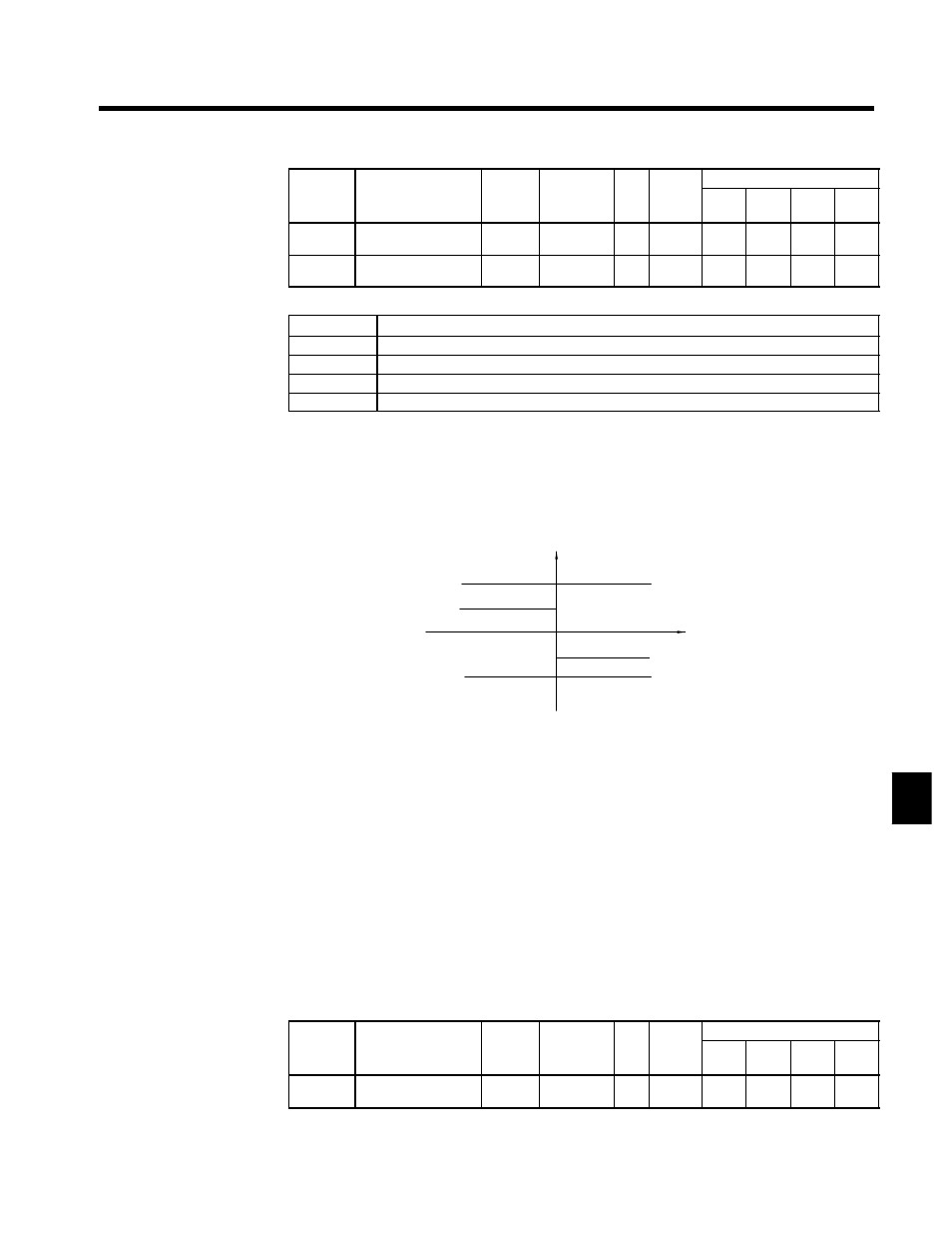
Figure 7.2 shows the relationship between the output torque and each torque limit.
Output torque
Forward direction
Reverse direction
Regenerative torque limit
Reverse torque limit
Motor speed
Reverse
Forward
Forward torque limit
Regenerative torque limit
Fig 7.2
Limiting Torque with Analog Inputs
D
When the forward torque limit has been set, the analog input signal acts as the limit value for torque
generated in the forward direction. The torque limit input is effective when torque is generated in the
forward direction even if the motor is operating in reverse (regenerative torque).
D
The torque limit is 100% of the motor’s rated torque when the analog input is at its maximum value (10
V or 20 mA). To increase the torque limit above 100%, set the input terminal’s gain above 100%. For
example, a gain of 150.0% would result in a torque limit of 150% of the motor’s rated torque with a 10
V or 20 mA analog input.
•
Gain for multi-function analog input, terminal 42: H3-06
•
Gain for frequency reference (current), terminal 39: H3-10
7.1.2 Adjusting Speed Feedback
With open-loop vector control, internal Inverter data is used to calculate the feedback value. The gain of
this automatic frequency regulator (AFR) operation can be fine-tuned according to motor response. (Nor-
mally it isn’t necessary to change the default setting.)
J
Speed Feedback Detection Control (AFR) Gain: C8-08
User
Change
during
Setting
Factory
Valid Access Levels
User
Constant
Number
Name
g
during
Opera-
tion
Setting
Range
Unit Factory
Setting
V/f
Control
V/f with
PG
Open
Loop
Vector
Flux
Vector
C8-08
AFR gain
x
0.00 to
10.00
Mul-
tiple
1.00
x
x
A
x
D
Normally it isn’t necessary to change this setting.
7