Yaskawa G5HHP Drive User Manual
Page 234
Advanced Operation
7.5.5 External Terminal Functions: H
7 - 70
PID Control Disable (Setting: 19)
OFF
Enables PID control.
ON
Disables PID control. (Normal Inverter control)
D
With this setting, the multi-function input switches between PID control and normal Inverter control.
This function can be used to perform trial operation or jog operation with normal inverter control (open-
loop control) and then switch to PID control (closed-loop control using feedback) after adjusting the
system. The PID disable function can also be used to switch to open-loop control when there is a problem
with the feedback value.
Constants Write Enable (Setting: 1B)
OFF
Write-protects all constants except for frequency monitor.
ON
Allows constants specified in Initialize mode to be changed.
D
With this setting, the multi-function input can be used to write-protect the Operator constants. When
the input is OFF, the Operation mode frequency can be monitored and the frequency can be changed
but other changes are prohibited.
Trim Control Increase and Decrease (Settings: 1C and 1D)
Trim Control In-
crease
ON
OFF
ON
OFF
Trim Control De-
crease
OFF
ON
ON
OFF
Output frequency
Reference frequency
+ trim control level
(d4-02)
Reference frequency --
trim control level
(d4-02)
Reference fre-
quency
Reference fre-
quency
D
The trim control increase function adds the level in d4-02 to the analog frequency reference.
D
The trim control decrease function subtracts the level in d4-02 to the analog frequency reference.
D
These functions are effective when the frequency reference is input from an analog input. These func-
tions must both be set at the same time or an OPE03 fault will occur. The analog frequency reference
won’t be changed when both the trim control increase and decrease inputs are ON. The output frequency
will be zero when the trim control decrease input is ON and the result of the subtraction is less than zero.
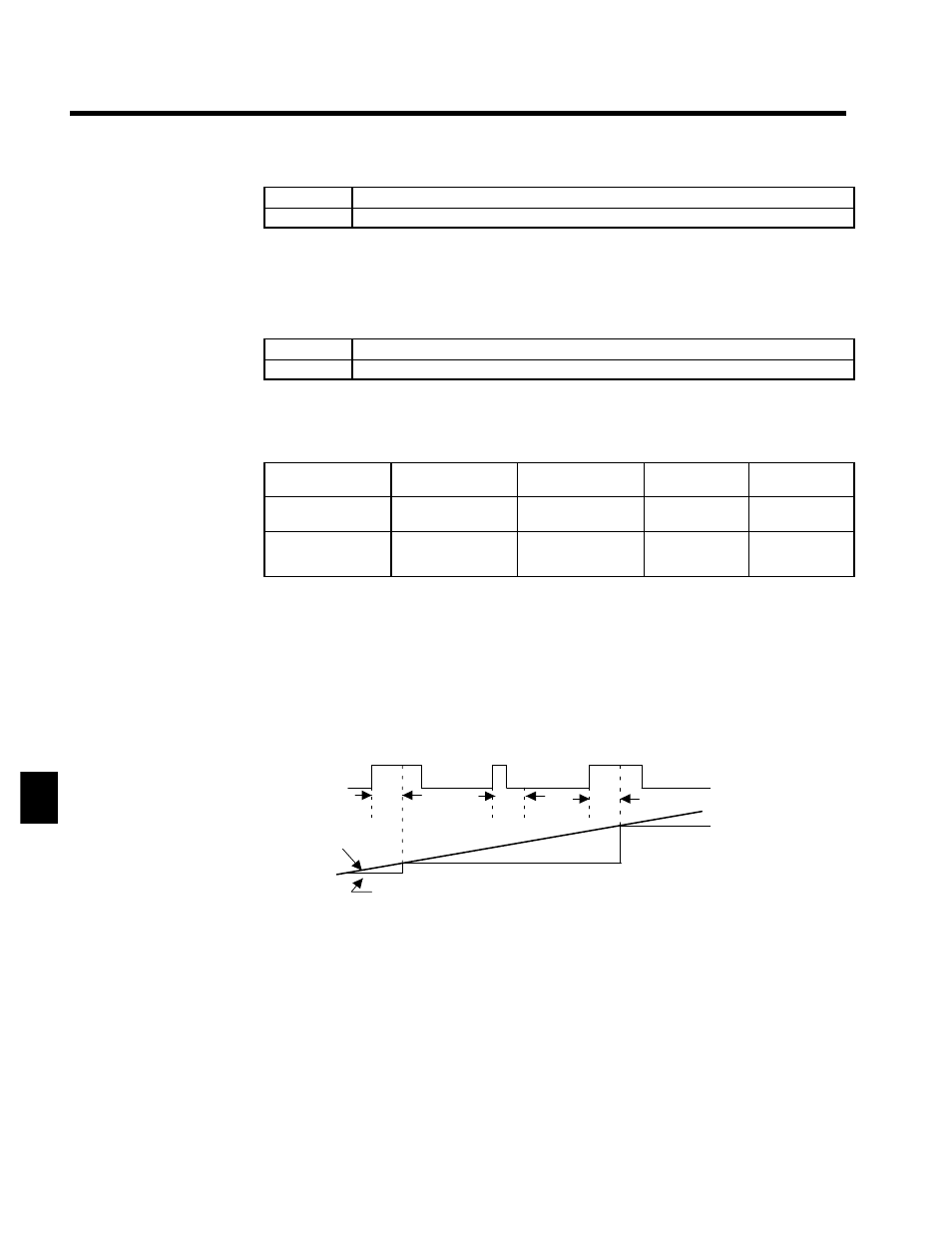
Analog Frequency Reference Sample/Hold (Setting: 1E)
D
The analog input value will become the frequency reference 100 ms after the multi-function input
closes.
Sample/hold
command
Analog input
Frequency
reference
CLOSED
100
ms
100
ms
100
ms
CLOSED
CLOSED
Fig 7.34
Analog Frequency Reference Sample/Hold
D
The analog frequency reference sample/hold function is valid only for terminals 36, 39, and 42 or for
the analog inputs from the AI-14U or AI-14B.
D
An OPE03 fault will occur if two or more of the following signals turn ON at the same time: acceleration/
deceleration ramp hold command (0A), up/down commands (10 or 11), trim control increase/decrease
commands (1C or 1D), and the analog frequency reference sample/hold command.
External Faults (Settings: 20 to 2F)
D
With this setting, the multi-function input can be used to stop the Inverter or output an alarm when a
malfunction or fault occurs in a peripheral device.
D
There are 16 external fault inputs available with all 16 combinations of the following variables. Select
the setting with the desired combination.
•
Input level:
Normally open or normally closed
7