3 wiring a pg speed control card, Pg-a2 (for v/f with pg feedback mode only) – Yaskawa G5HHP Drive User Manual
Page 57
3.7 Installing and Wiring PG Speed Control Cards
3 - 17
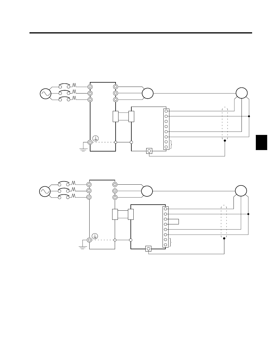
3.7.3 Wiring a PG Speed Control Card
Wiring examples are provided in the following illustrations for the PG Speed Control Cards.
J
PG-A2 (For V/f with PG Feedback Mode Only)
12 V Voltage Input
Three-phase, 400 VAC
(575 VAC)
VS-616G5
IM
PG
PG-A2
4CN
4CN
+12 V power supply
0 V power supply
12 V voltage output (A/B phase)
Pulse 0 V
Pulse monitor output
TA1
E
TA2 (E)
1
2
3
4
5
6
7
8
R/L1
S/L2
T/L3
U/T1
V/T2
W/T3
E
Fig 3.9
Wiring a 12 V Voltage Input
Open Collector Input
PG
Open collector output (A/B phase)
Three-phase, 400 VAC
(575 VAC)
VS-616G5
4CN
E
R/L1
S/L2
T/L3
U/T1
V/T2
W/T3
IM
PG-A2
4CN
TA1
E
TA2 (E)
1
2
3
4
5
6
7
8
+12 V power supply
0 V power supply
Pulse 0 V
Pulse monitor output
D
Shielded twisted-pair wires must be used for signal lines.
D
Do not use the pulse generator’s power supply for anything other than the
pulse generator (encoder). Using it for another purpose can cause malfunctions
due to noise.
D
The length of the pulse generator’s wiring must not be more than 100 meters.
Fig 3.10
Wiring an Open-collector Input
3