Yaskawa G5HHP Drive User Manual
Page 152
Basic Operation
6.4.4 Speed Control (ASR) Structure
6 - 34
User
Change
during
Setting
Factory
Valid Access Levels
User
Constant
Number
Name
g
during
Opera-
tion
Setting
Range
Unit
Factory
Setting
V/f
Control
V/f with
PG
Open
Loop
Vector
Flux
Vector
C5-03
ASR proportional
(P) gain 2
f
0.00 to
300.00
Multi-
ple
20.00
x
B
x
B
C5-04
ASR integral (I)
time 2
f
0.000 to
10.000
s
0.500
x
B
x
B
C5-07
ASR switching fre-
quency
f
0.0 to 150.0
Hz
0.0
x
x
x
A
D
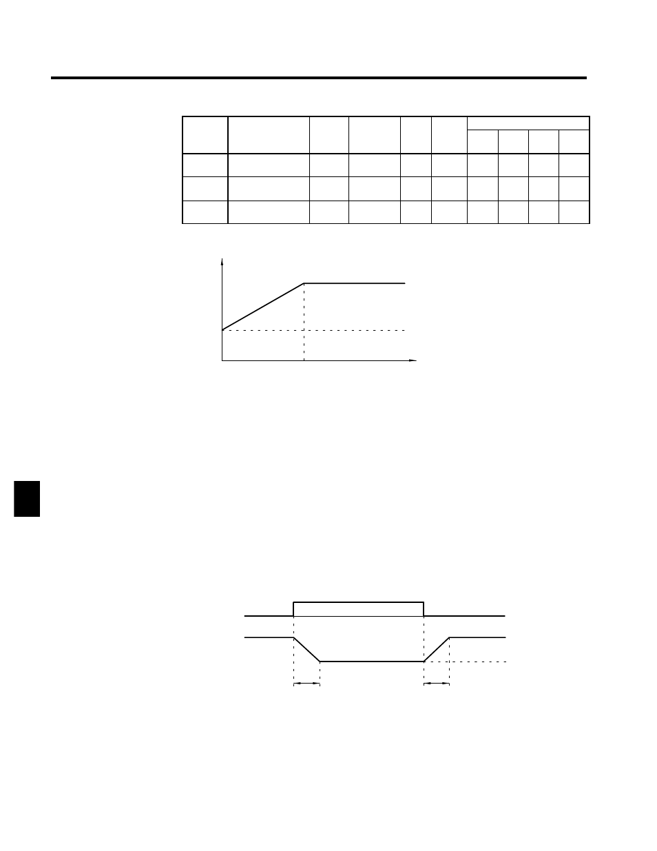
Figure 6.15 shows how the proportional gain and integral time approach the ASR proportional gain 2 and
ASR integral time 2 linearly.
P, I
0
C5-07
Motor speed (Hz)
P=C5-01
I=C5-02
P=C5-03
I=C5-04 (Low speed)
If C5-07 is set to 0.0, ASR proportional gain 1 and ASR integral
time 1 are used for the proportional gain and integral time at all
frequencies.
Fig 6.15
Gain Settings at Low Frequencies
J
Multi-function Input Settings: H1-01 (Terminal 11) to H1-06 (Terminal 16)
ASR Integral Reset Setting: “E”
D
When one of the multi-function inputs is set to “E,” the input can be used to switch the speed control
loop between P control and PI control.
D
P control (integral reset) is used when the multi-function input is ON.
ASR Proportional Gain Switch Setting: “77”
D
When one of the multi-function inputs is set to “77,” the input can be used to switch between proportion-
al gain 1 and proportional gain 2.
D
Proportional gain 2 (C5-03) is used when the multi-function input is ON. This input has higher priority
than the ASR switching frequency set in C5-07.
ASR Gain Switch
signal (a multi-func-
tion input)
Proportional gain
(P)
ON
OFF
C5-02
Proportional gain
determined by mo-
tor speed.
C5-03 gain setting
C5-02
The gain is changed linearly in integral time 1 (C5-02). The integral
time setting isn’t switched.
Fig 6.16
ASR Proportional Gain Switch
6