2 main circuit configurations, 3 precautions for wiring main circuit power input, Wiring – Yaskawa G5HHP Drive User Manual
Page 50: Fig 3.5 short-circuit bus bar connections
Wiring
3.4.3 Precautions for Wiring Main Circuit Power Input
3 - 10
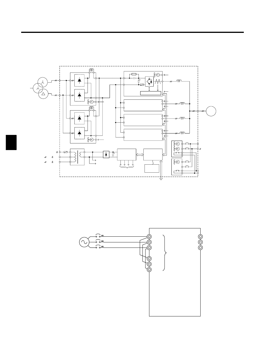
3.4.2 Main Circuit Configurations
The main circuit configuration of the CIMR-G5A4800 is shown below.
Gate Drive
Power supply
Power supply
200 VAC
200 VAC
200 VAC
1INV
Power supply
200 VAC
Power supply
200 VAC
M
Control
circuit
Power supply
to control cir-
cuit/Gate drive
Operator
200/
r/
To fan and MC
To Gate Drive
MC
2INV
3INV
4INV
1CONV
U/T1
V/T2
W/T3
r200
200
F1
F2
200 VAC
200
2
400/
400
2
1
R1/L11
S1/L21
T1/L31
R/L1
S/L2
T/L3
200 VAC
2CONV
I/O
Fig 3.4
Main Circuit Configuration (CIMR-G5A4800)
3.4.3 Precautions for Wiring Main Circuit Power Input
At the time of shipment, short-circuit bus bars are provided between R/L1 and R1/L11, S/L2 and S1/L21,
and between T/L3 and T1/L31 on the main circuit power input terminal. Remove these short-circuit bus bars
when applying 12-phase rectification.
R/L1
S/L2
T/L3
U/T1
V/T2
W/T3
R1/L11
S1/L21
T1/L31
At the time of ship-
ment, short-circuit
bus bars are con-
nected between
these terminals.
Fig 3.5
Short-circuit Bus Bar Connections
3