2 minor fault detection – Yaskawa G5HHP Drive User Manual
Page 316
Troubleshooting
9.1.2 Minor Fault Detection
9 - 6
9.1.2 Minor Fault Detection
Minor faults are a type of Inverter protection function that do not operate the fault contact output and are auto-
matically returned to their original status once the cause of the minor fault has been removed.
The Digital Operator display blinks and the minor fault is output from the multi-function outputs (H2-01 to
H2-03).
Take appropriate countermeasures according to the table below.
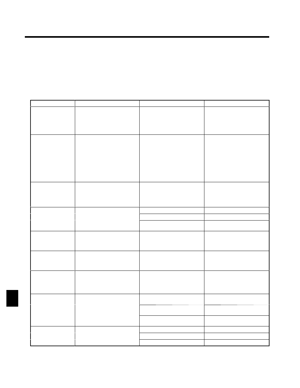
Table 9.2 Minor Fault Displays and Processing
Minor fault display
Meaning
Probable causes
Corrective Actions
EF (blinking)
External Fault
Forward/Reverse Run Commands
Input Together
Both the forward and reverse run
commands have been ON for more
than 0.5 s.
----
Check the sequence of the forward
and reverse run commands.
;
Since the rotational direction is un-
known, the motor will be deceler-
ated to a stop when this minor fault
occurs.
UV (blinking)
DC Bus Undervolt
Main Circuit Undervoltage
The following conditions occurred
when there was no Run signal.
S
The main circuit DC voltage was be-
low the undervoltage detection lev-
el (L2-05).
S
The surge current limiting contactor
opened.
S
The control power supply voltage
when below the CUV level.
See causes for UV1, UV2, and UV3
faults.
See corrective actions for UV1, UV2,
and UV3 faults.
OV (blinking)
Overvoltage
Main Circuit Overvoltage
The main circuit DC voltage exceeded
the overvoltage detection level.
400-V class: Approx. 800 V
800 V class: Approx. 990 V
The power supply voltage is too high.
Decrease the voltage so it’s within
specifications.
Cooling Fin Overheating
The ambient temperature is too high.
Install a cooling unit.
OH (blinking)
H
i k O
The temperature of the Inverter’s
cooling fins exceeded the setting in
There is a heat source nearby.
Remove the heat source.
Heatsink Over tmp
cooling fins exceeded the setting in
L8-02.
The Inverter cooling fan has stopped.
Replace the cooling fan. (Contact your
Yaskawa representative.)
OH2 (blinking)
Over Heat 2
Inverter Overheating Pre-alarm
An OH2 alarm signal (Inverter over-
heating alarm signal) was input from a
multi-function input.
----
Clear the multi-function input’s over-
heating alarm input.
OL3 (blinking)
Overtorque Det 1
Overtorque 1
There has been a current greater than
the setting in L6-02 for longer than
the setting in L6-03.
----
S
Make sure that the settings in L6-02
and L6-03 are appropriate.
S
Check the mechanical system and
correct the cause of the overtorque.
OL4 (blinking)
Overtorque Det 2
Overtorque 2
There has been a current greater than
the setting in L6-05 for longer than
the setting in L6-06.
----
S
Make sure that the current setting in
L6-05 and time setting in L6-06 are
appropriate.
S
Check the mechanical system and
correct the cause of the overtorque.
Overspeed
The speed has been greater than the
i
i F1 08 f l
h
h
Overshooting/undershooting are oc-
curring.
Adjust the gain again.
OS (blinking)
Over speed
The speed has been greater than the
setting in F1-08 for longer than the
setting in F1-09.
The reference speed is too high.
Check the reference circuit and refer-
ence gain.
O e speed
The settings in F1-08 and F1-09 aren’t
appropriate.
Check the settings in F1-08 and F1-09.
PGO (blinking)
The PG is disconnected.
There is a break in the PG wiring.
Fix the broken/disconnected wiring.
PGO (blinking)
PG open
The Inverter is outputting a frequency,
but PG pulses aren’t being input.
The PG is wired incorrectly.
Fix the wiring.
PG open
but PG pulses aren t being input.
Power isn’t being supplied to the PG.
Supply power to the PG properly.
9