Yaskawa G5HHP Drive User Manual
Page 215
7.5 Common Functions
7 - 51
•
When “1.0” is set, this function compensates for the rated slip that has been set, by the rated torque
output.
•
With flux vector control, this becomes the gain to compensate for slip caused by motor temperature
variation. (Refer to Slip Compensation Gain: C3-01 under 7.3.6.)
Motor Slip Compensation Gain Adjustment Procedure
1. Correctly set the motor rated slip (constant E2-02) and the motor no-load current (constant E2-03).
•
The motor rated slip can be calculated by means of the following equation, using the numbers that
are shown on the motor nameplate.
Motor rated slip =
Motor rated frequency (Hz) -- rated speed (r/min) x motor (No. of poles) / 120
•
Set the values at the rated voltage and rated frequency for the motor no-load current. With vector
control, the motor rated slip is automatically set by autotuning.
2. Set the slip compensation gain (constant C3-01 to “1.0.” (If it is set to “0.0,” slip compensation will be
disabled.)
3. Operate with a load, measure the speed, and adjust the slip compensation gain (in increments of 0.1).
•
If the speed is lower than the target value, increase the slip compensation gain.
•
If the speed is higher than the target value, decrease the slip compensation gain.
Slip Compensation Primary Delay Time: C3-02
User
Change
during
Setting
Factory
Valid Access Levels
User
Constant
Number
Name
g
during
Opera-
tion
Setting
Range
Unit Factory
Setting
V/f
Control
V/f with
PG
Open
Loop
Vector
Flux
Vector
C3-02
Slip compensation
primary delay time
x
0 to 10000
ms
200 *
A
x
A
x
* When the control method is switched, the values change as follows:
V/f control: 2,000; open-loop vector: 200
D
This constant does not normally need to be set. Adjust the slip compensation primary delay time if the
motor slip compensation responsiveness is low, or if the speeds are unstable.
•
If responsiveness is low, lower the setting.
•
If speeds are unstable, raise the setting.
Slip Compensation Limit: C3-03
User
Change
during
Setting
Factory
Valid Access Levels
User
Constant
Number
Name
g
during
Opera-
tion
Setting
Range
Unit Factory
Setting
V/f
Control
V/f with
PG
Open
Loop
Vector
Flux
Vector
C3-03
Slip compensation
limit
x
0 to 250
%
200
A
x
A
x
D
Constant C3-03 sets the slip compensation limit as a percentage of motor rated slip (E2-02), with the
motor rated slip taken as 100%.
D
If the speed is lower than the target value and does not change even when the slip compensation gain
is adjusted, it is possible that the slip compensation limit has been reached. Raise the limit and then check
again. Make sure, however, that the value of the sum of the reference frequency and the slip compensa-
tion limit does not exceed the speed capacity of the machinery.
D
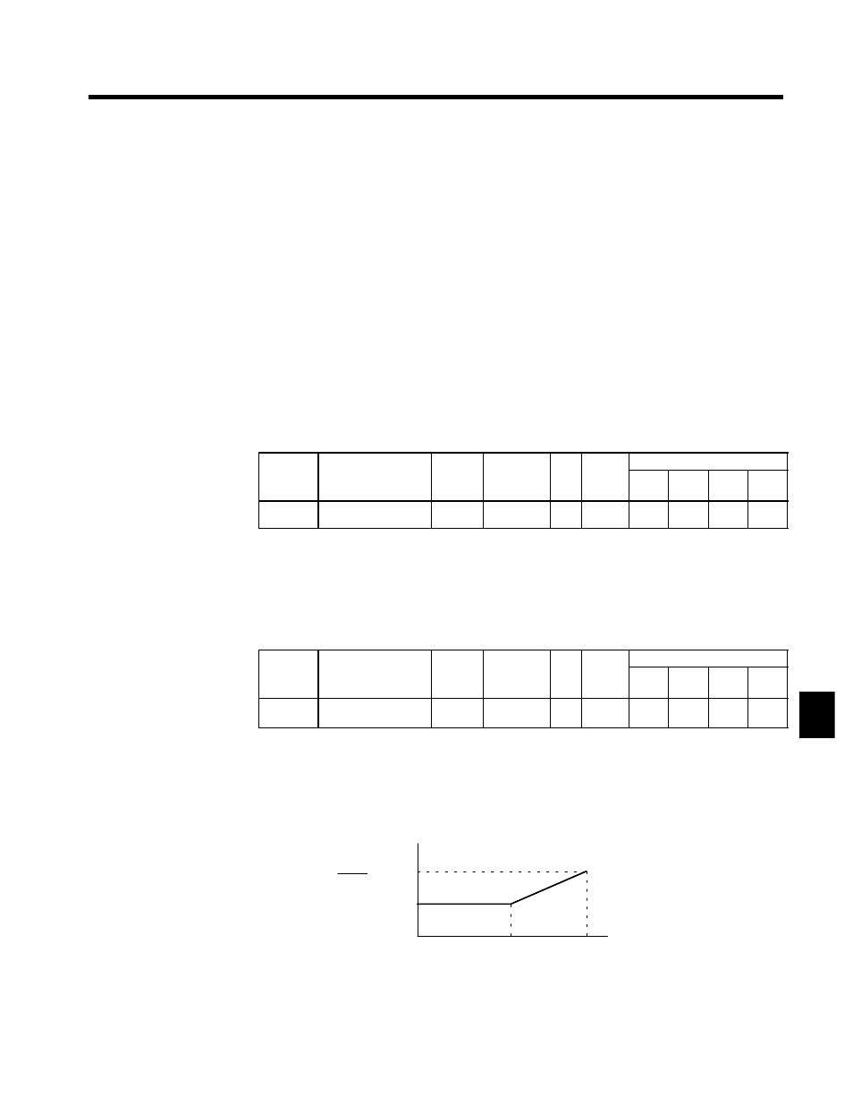
The limit is as shown in Figure 7.25 in the constant torque and constant output areas.
Slip compensation limit
C3-03
E1-06
E1-04
Output frequency
E1-04
E1-06 ×
C3-03
E1-06: Base frequency
E1-04: Maximum output frequency
Fig 7.25
Slip Compensation Limit
7