Yaskawa G5HHP Drive User Manual
Page 255
7.5 Common Functions
7 - 91
Stall Prevention Level During Running: L3-06
User
Change
during
Setting
Factory
Valid Access Levels
User
Constant
Number
Name
g
during
Opera-
tion
Setting
Range
Unit Factory
Setting
V/f
Control
V/f with
PG
Open
Loop
Vector
Flux
Vector
L3-06
Stall prevention level
during running
x
30 to 200
%
160
B
B
x
x
D
This setting is valid when L3-05 is set to 1 or 2.
D
Normally it isn’t necessary to change this setting.
D
Decrease this setting when the motor capacity is small compared to the Inverter capacity or stalling oc-
curs when the motor is operated with the factory setting.(Set this current value as a percentage of the
Inverter’s rated current, i.e., 100% corresponds to the Inverter’s rated current.)
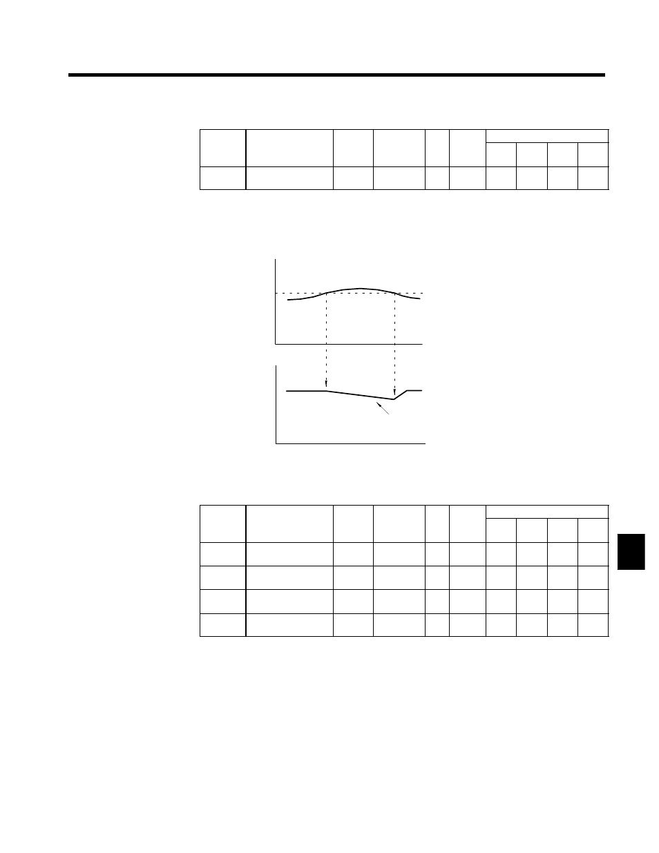
Output current
Time
Output frequency
Time
The output frequency is controlled to prevent
stalling.
Deceleration rate: C1-02 or C1-04
L3-06 (Run stall prevention level)
Fig 7.46
Run Stall Prevention Function: L3-05 = 1 or 2
J
Frequency Detection Settings: L4-01 to L4-05
User
Change
during
Setting
Factory
Valid Access Levels
User
Constant
Number
Name
g
during
Opera-
tion
Setting
Range
Unit Factory
Setting
V/f
Control
V/f with
PG
Open
Loop
Vector
Flux
Vector
L4-01
Speed agree detection
level
x
0.0 to 150.0
Hz
0.0
B
B
B
B
L4-02
Speed agree detection
width
x
0.0 to 20.0
Hz
2.0
B
B
B
B
L4-03
Speed agree detection
level (+/--)
x
--150.0 to
+150.0
Hz
0.0
A
A
A
A
L4-04
Speed agree detection
width (+/--)
x
0.0 to 20.0
Hz
2.0
A
A
A
A
D
Set these constants when outputting one of the frequency agree or frequency detection signals from a
multi-function output. Table 7.13 shows the relationship between these constants and the output signals.
D
Motor speed is detected at Flux Vector Control.
7