4 wiring main circuit terminals, 1 main circuit terminal functions – Yaskawa G5HHP Drive User Manual
Page 49
3.4 Wiring Main Circuit Terminals
3 - 9
3.4 Wiring Main Circuit Terminals
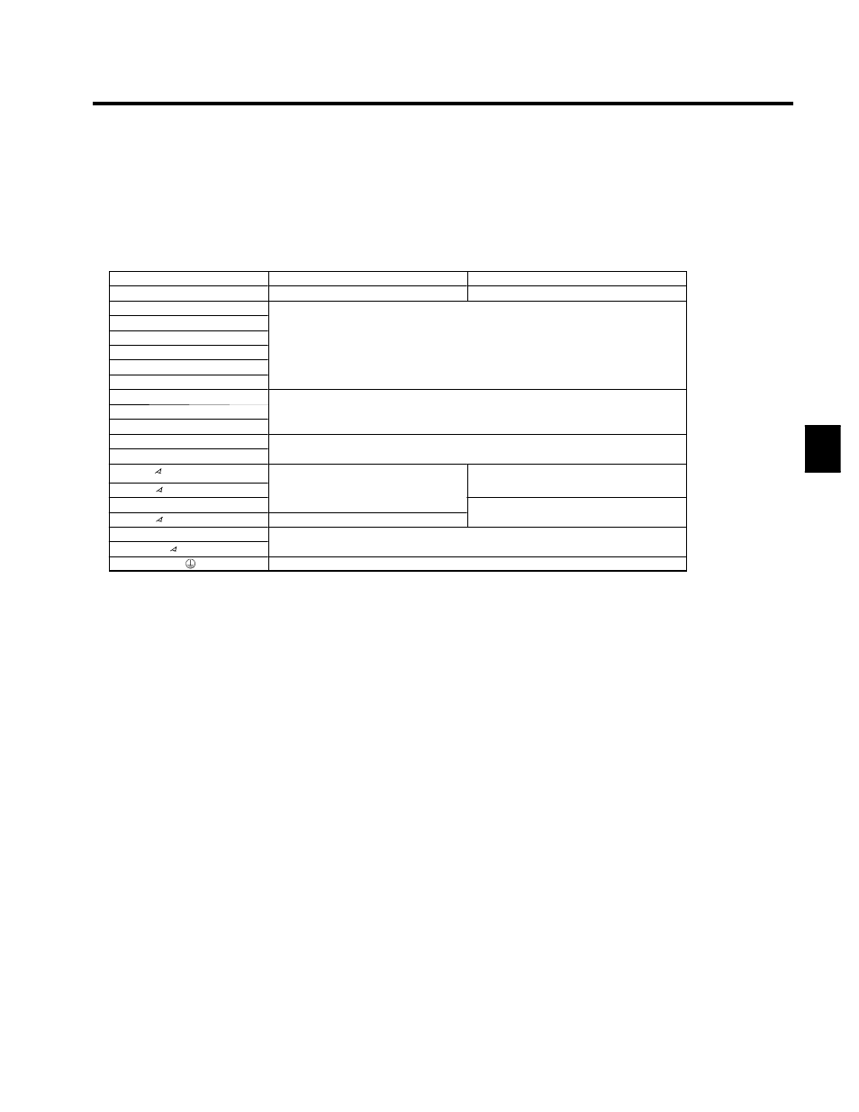
3.4.1 Main Circuit Terminal Functions
Main circuit terminal functions are summarized according to terminal symbols in Table 3.1. Wire the termi-
nals correctly for the desired purposes.
Table 3.1 Main Circuit Terminal Functions
Voltage Class
400-V Class
575-V Class
CIMR-G5Aj
4200 to 4800
5300 to 512C
R/L1
S/L2
Main Circuit Power Inputs
T/L3
Main Circuit Power Inputs
(At the time of shipment, short-circuit bus bars are connected between R/L1 and R1/L11,
R1/L11
(At the time of shipment, short-circuit bus bars are connected between R/L1 and R1/L11,
S/L2 and S1/L21, and between T/L3 and T1/L31. Remove these short-circuit bus bars
h
l i
12 h
tifi ti
)
S1/L21
/
/
,
/
/
when applying 12-phase rectification.)
T1/L31
U/T1
V/T2
Inverter Outputs
W/T3
Inverter Outputs
¨
1
For connecting the Braking Unit
©
For connecting the Braking Unit
200/ℓ
2
200
Control Power Inputs
--
400/ℓ
2
400
Control Power Inputs
(For Module fan power input)
--
r/ℓ
1
(For Module fan power input)
Control Power Inputs
575/ℓ
2
575
--
Control Power Inputs
(For Module fan power input)
r200
Power input to the Inverter Panel ventilation fan
200
Power input to the Inverter Panel ventilation fan
Ground
3