Motor setup: e2 – Yaskawa G5HHP Drive User Manual
Page 286
User Constants
8.2.4 Motor Constant Constants: E
8 - 20
* 1. These are values for a 400-V class Inverter. Multiply the values by approx. 1.5 for the 575-V class Inverter.
* 2. When the control method is changed, the Inverter reverts to factory settings. (The open loop vector control factory settings will
be displayed.)
* 3. E1-11 and E1-12 are disregarded when set to 0.0.
* 4. E1-13 is set to the same value as E1-05 by autotuning.
J
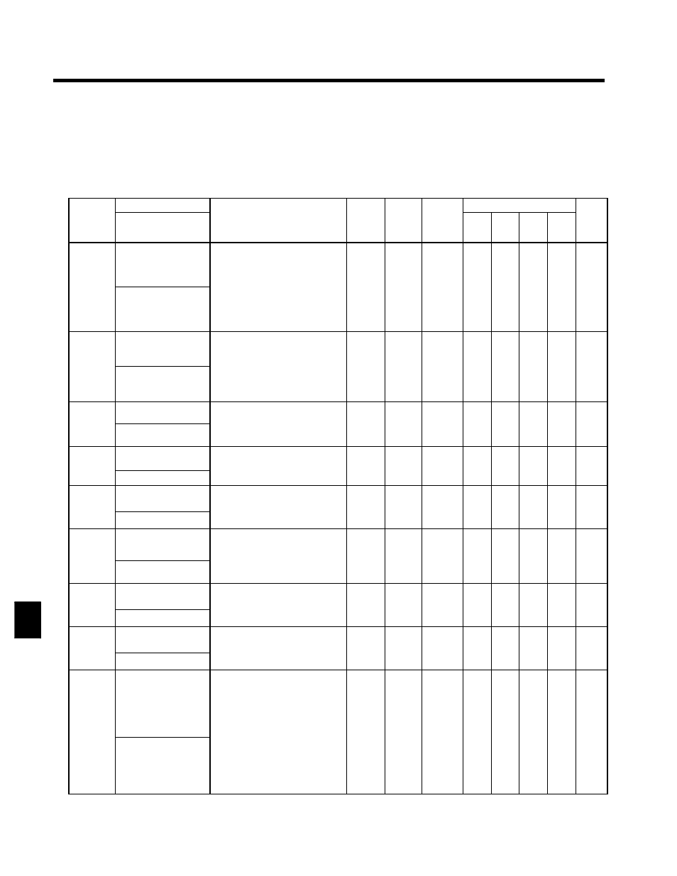
Motor Setup: E2
C
t t
Name
S tti
F t
Change
Control Methods
Constant
Number
Display
Description
Setting
Range
Factory
Setting
Change
during
Opera-
tion
V/f
V/f
with
PG
Open
Loop
Vector
Flux
Vector
Page
E2-01
Motor rated current
Sets the motor rated current in 1 A
units.
;
These set values will become the
reference values for motor
protection torque limits and
37.0 to
740.0
370.0
x
Q
Q
Q
Q
6 - 21
E2-01
Motor Rated FLA
protection, torque limits and
torque control.
These values will automatically
be set if they were set during au-
totuning.
740.0
*2
370.0
*1
x
Q
Q
Q
Q
6 21
6 - 39
E2-02
Motor rated slip
Sets the motor rated slip in Hz
units.
;
These set values will become the
f
l
f
li
0.00 to
1.30
x
A
A
Q
Q
7 - 13
E2-02
Motor Rated Slip
;
reference values for slip com-
pensation.
These values will be automati-
cally set during autotuning.
0.00 to
20.00
1.30
*1
x
A
A
Q
Q
7 13
7 - 30
E2-03
Motor no-load current Sets the motor no-load current in 1
A units.
0.00 to
96.0
x
A
A
Q
Q
7 - 13
E2-03
No-Load Current
A units.
;
These values will be automatical-
ly set during autotuning.
0.00 to
2000.0
96.0
*1
x
A
A
Q
Q
7 13
7 - 31
E2-04
Number of motor
poles
Sets the number of motor poles.
;
These values will automatically
2 to 48
4
x
x
Q
x
Q
6 - 39
7 31
E2 04
Number of Poles
;
These values will automatically
be set during autotuning.
2 to 48
4
x
x
Q
x
Q
7 - 31
E2-05
Motor line-to-line re-
sistance
Sets the motor phase-to-phase re-
sistance in Ω units.
;
Th
l
ill b
t
ti l
0.000 to
65 000
0.020
*1
x
A
A
A
A
7 - 13
7 31
E2 05
Term Resistance
;
These values will be automatical-
ly set during autotuning.
65.000
*1
x
A
A
A
A
7 - 31
E2-06
Motor leak induc-
tance
Sets the voltage drop due to motor
leakage inductance as a percentage
of the motor rated voltage.
0.0 to
30 0
5.0
x
x
x
A
A
7 - 9
7 31
E2 06
Leak Inductance
g
;
These values will be automatical-
ly set during autotuning.
30.0
5.0
x
x
x
A
A
7 - 31
E2-07
Motor iron-core satu-
ration coefficient 1
Sets the motor iron-core saturation
coefficient at 50% of magnetic flux.
;
Th
l
ill b
t
ti l
0.00 to
0 50
0.50
x
x
x
A
A
7 - 9
7 - 32
E2 07
Saturation Comp 1
;
These values will be automatical-
ly set during autotuning.
0.50
0.50
x
x
x
A
A
7 - 32
E2-08
Motor iron-core satu-
ration coefficient 2
Sets the motor iron-core saturation
coefficient at 75% of magnetic flux.
;
Th
l
ill b
t
ti l
0.00 to
0 75
0.75
x
x
x
A
A
7 - 9
7 32
E2 08
Saturation Comp 2
;
These values will be automatical-
ly set during autotuning.
0.75
0.75
x
x
x
A
A
7 - 32
E2-09
Motor mechanical
loss
Sets motor mechanical loss as a
percentage of motor rated output
(W).
;
Usually setting is not necessary.
Adjust in the following circum-
stances:
S
When torque loss is large due to
0.0 to
10 0
0.0
x
x
x
x
A
7 - 32
E2 09
Mechanical Loss
S
When torque loss is large due to
motor bearing.
S
When the torque loss in the pump
or fan is large.
The set mechanical loss will com-
pensate for torque.
10.0
0.0
x
x
x
x
A
7 - 32
8