Yaskawa G5HHP Drive User Manual
Page 296
User Constants
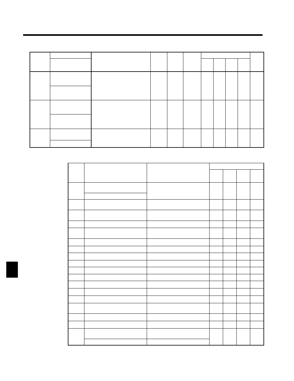
8.2.6 Terminal Constants: H
8 - 30
Constant
Number
Page
Control Methods
Change
during
Opera-
tion
Factory
Setting
Setting
Range
Description
Name
Constant
Number
Page
Flux
Vector
Open
Loop
Vector
V/f
with
PG
V/f
Change
during
Opera-
tion
Factory
Setting
Setting
Range
Description
Display
H3-10
Gain (terminal 39)
Sets the input gain (level) when ter-
minal 39 is 10 V (20 mA).
Set according to the 100% value on
0.0 to
100 0
f
A
A
A
A
6 6
H3-10
Terminal 39 Gain
Set according to the 100% value on
page 7 - 79.
If H3-09 = “1F” the setting in
H3-02 is used.
0.0 to
1000.0
100.0
f
A
A
A
A
6 - 6
H3-11
Bias (terminal 39)
Sets the input gain (level) when ter-
minal 39 is 0 V (4 mA).
Set according to the 100% value on
--100.0
to
0 0
f
A
A
A
A
6 6
H3-11
Terminal 39 Bias
Set according to the 100% value on
page 7 - 79.
If H3-09 = “1F” the setting in
H3-03 is used.
to
+100.0
0.0
f
A
A
A
A
6 - 6
H3-12
Analog input filter
time constant
Sets terminals 36, 39, 42 to primary
delay filter time constant, in sec-
onds units
0.00 to
2 00
0.00
x
A
A
A
A
6 - 7
H3 12
Filter Avg Time
onds units.
;
Effective for noise control etc.
2.00
0.00
x
A
A
A
A
6 - 7
H3-05 and H3-09 Settings
Control Methods
Setting
Function
Contents
V/f
V/f
with
PG
Open
Loop
Vector
Flux
Vector
0
H3-05: Auxiliary frequency refer-
ence
Maximum output frequency
f
f
f
f
0
H3-09: “0” cannot be set
Maximum output frequency
f
f
f
f
1
Frequency gain
Frequency reference (voltage) com-
mand value
f
f
f
f
2
Frequency bias
Maximum output frequency (added to
H3-03)
f
f
f
f
4
Voltage bias
Motor rated voltage (E1-05)
f
f
x
x
5
Accel/decel change (reduction coeffi-
cient)
Set acceleration and deceleration
times (C1-01 to C1-08)
f
f
f
f
6
DC injection braking current
Inverter rated output current
f
f
f
x
7
Overtorque detection level
Motor rated torque
f
f
f
f
8
Stall prevention level during run
Inverter rated current
f
f
x
x
9
Frequency reference lower limit level Maximum output frequency
f
f
f
f
A
Jump frequency
Maximum output frequency
f
f
f
f
B
PID feedback
Maximum output frequency
f
f
f
f
10
Forward torque limit
Motor’s rated torque
x
x
f
f
11
Reverse torque limit
Motor’s rated torque
x
x
f
f
12
Regenerative torque limit
Motor’s rated torque
x
x
f
f
13
Torque reference/torque limit at
speed control
Motor’s rated torque
x
x
x
f
14
Torque compensation bias
Motor’s rated torque
x
x
x
f
15
Forward/reverse torque limit
Motor’s rated torque
x
x
f
f
1F
H3-05: Not used (terminal 39: fre-
quency reference)
--
f
f
f
f
1F
H3-09: Frequency reference
Maximum output frequency
f
f
f
f
8