Yaskawa G5HHP Drive User Manual
Page 189
7.3 Flux Vector Control
7 - 25
D
The functions of H3-05 and H3-09 are listed in Table 7.12.
D
Set torque compensation (setting 14) for the input terminal that isn’t set to torque reference (setting 13).
User
Change
during
Setting
Factory
Valid Access Levels
User
Constant
Number
Name
g
during
Opera-
tion
Setting
Range
Unit Factory
Setting
V/f
Control
V/f with
PG
Open
Loop
Vector
Flux
Vector
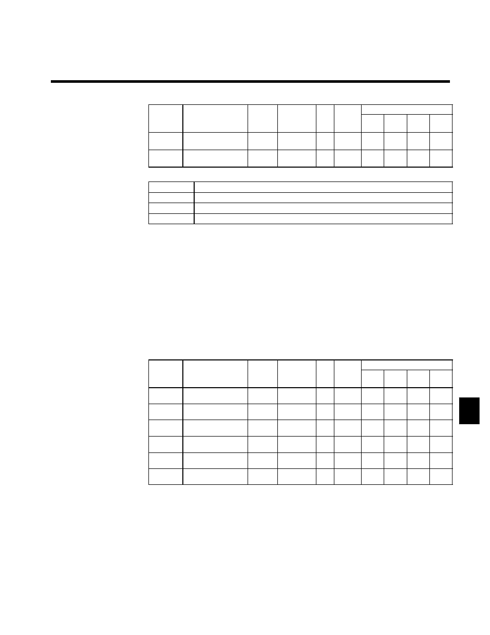
H3-04
Signal level selection
(terminal 42)
x
0, 1
--
0
B
B
B
B
H3-08
Signal level selection
(terminal 39)
x
0 to 2
--
2
A
A
A
A
D
Settings
Setting
Function
0
0 to +10 V input (When H3-08 is being set, be sure to disconnect jumper wire J1.)
1
0 to ±10 V input (When H3-08 is being set, be sure to disconnect jumper wire J1.)
2
4 to 20 mA input (H3-08 only)
D
Set the proper signal level for the torque compensation bias that you want to input.
D
The direction of the torque compensation bias is determined by the sign (polarity) of the signal that is
input. It is not determined by the direction of the run command (forward/reverse).
•
+Voltage (or current): Forward torque compensation
(generally counter-clockwise; axis side)
•
--Voltage:
Reverse torque compensation (generally clockwise; axis side)
Since the polarity of the voltage input determines the direction, only forward torque compensation can
be input when the “0 to +10 V” or “4 to 20 mA” signal level has been selected. If you want to input re-
verse torque compensation, be sure to select the “0 to ±10 V” signal level.
D
When supplying a voltage input to the frequency reference current input (terminal 39), be sure to discon-
nect jumper wire J1 on the control board. If the jumper wire isn’t disconnected, the input resistor will
be destroyed. Refer to Figure 7.10 for a diagram of the control board.
Adjusting the Gain/Bias of the Analog Inputs: H3-02, -03, -06, -07, -10, -11
D
Adjust the gain and bias for the frequency reference (voltage), frequency reference (current), and multi-
function analog inputs according to the input specifications for each input.
User
Change
during
Setting
Factory
Valid Access Levels
User
Constant
Number
Name
g
during
Opera-
tion
Setting
Range
Unit Factory
Setting
V/f
Control
V/f with
PG
Open
Loop
Vector
Flux
Vector
H3-02
Gain (terminal 36)
f
0.0 to
1000.0
%
100.0
B
B
B
B
H3-03
Bias (terminal 36)
f
--100.0 to
+100.0
%
0.0
B
B
B
B
H3-06
Gain (terminal 42)
f
0.0 to
1000.0
%
100.0
B
B
B
B
H3-07
Bias (terminal 42)
f
--100.0 to
+100.0
%
0.0
B
B
B
B
H3-10
Gain (terminal 39)
f
0.0 to
1000.0
%
100.0
A
A
A
A
H3-11
Bias (terminal 39)
f
--100.0 to
+100.0
%
0.0
A
A
A
A
D
Adjust the gain so that the maximum signal level corresponds to the maximum frequency or the motor’s
rated torque, as follows.
•
When the input terminal is used for frequency reference:
A 10 V (20 mA) input indicates a frequency reference that is 100% of the max. output frequency.
•
When the input terminal is used for torque reference:
A 10 V (20 mA) input indicates a torque reference that is 100% of the motor’s rated torque.
•
When the input terminal is used for torque compensation:
A 10 V (20 mA) input indicates a torque compensation that is 100% of the motor’s rated torque.
D
Adjust the bias so that the minimum signal level corresponds to the maximum frequency or the motor’s
rated torque, as follows.
•
When the input terminal is used for frequency reference:
A 0 V (4 mA) input indicates a frequency reference that is 100% of the max. output frequency.
7