2 tuning constants: c – Yaskawa G5HHP Drive User Manual
Page 214
Advanced Operation
7.5.2 Tuning Constants: C
7 - 50
7.5.2 Tuning Constants: C
J
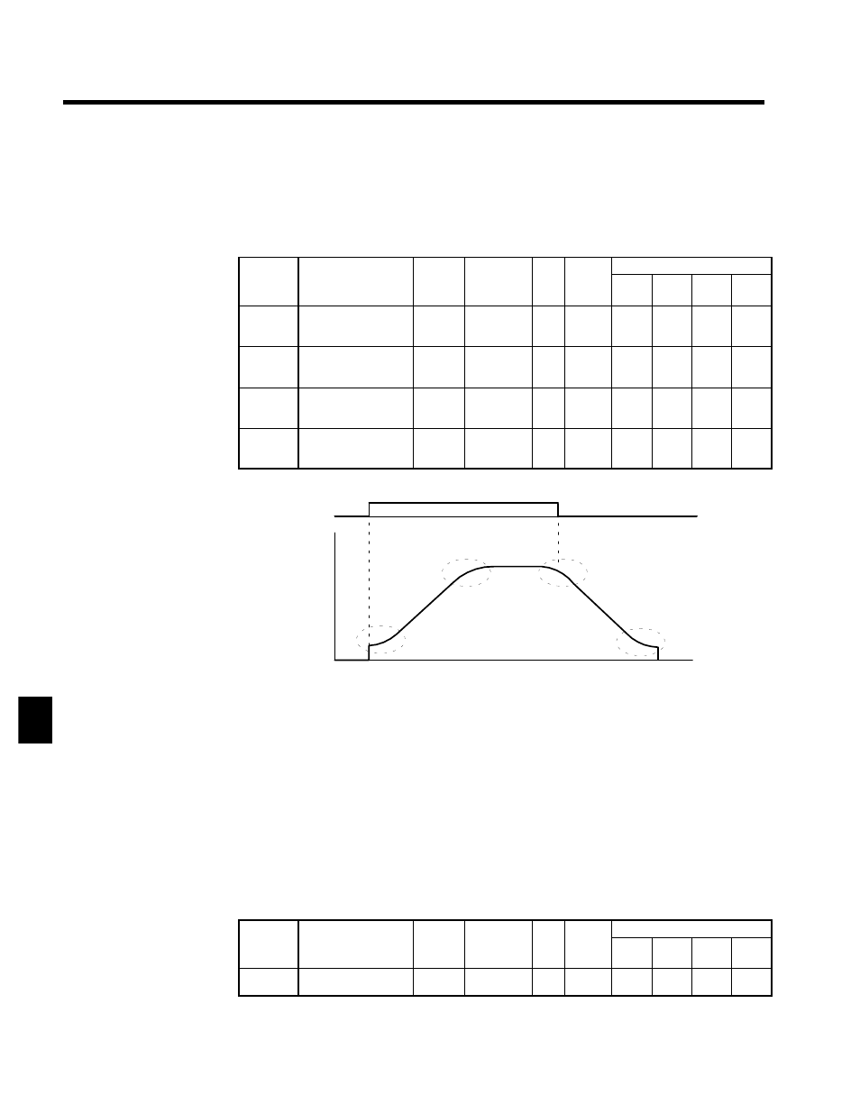
S-curve Characteristic Function: C2-01 to C2-04
D
Using the S-curve characteristic function for acceleration and deceleration can reduce shock to the ma-
chinery when stopping and starting.
D
With the Inverter, S-curve characteristic times can be set respectively for beginning acceleration, ending
acceleration, beginning deceleration, and ending deceleration.
User
Change
during
Setting
Factory
Valid Access Levels
User
Constant
Number
Name
g
during
Opera-
tion
Setting
Range
Unit Factory
Setting
V/f
Control
V/f with
PG
Open
Loop
Vector
Flux
Vector
C2-01
S-curve characteristic
time at acceleration
start
x
0.00 to 2.50
s
0.20
A
A
A
A
C2-02
S-curve characteristic
time at acceleration
end
x
0.00 to 2.50
s
0.20
A
A
A
A
C2-03
S-curve characteristic
time at deceleration
start
x
0.00 to 2.50
s
0.20
A
A
A
A
C2-04
S-curve characteristic
time at deceleration
end
x
0.00 to 2.50
s
0.00
A
A
A
A
D
The relation between these constants is shown in Figure 7.24.
Output
frequency
C2-01
C2-02
C2-03
C2-04
Time
Run command
OFF
ON
Fig 7.24
Setting S-curve Characteristics
D
When the S-curve characteristic time is set, the acceleration and deceleration times will be lengthened
as follows:
•
Acceleration time =
Selected acceleration time + (S-curve at beginning of acceleration + S-curve at end of acceleration)
/ 2
•
Deceleration time =
Selected deceleration time + (S-curve at beginning of deceleration + S-curve at end of deceleration)
/ 2
J
Motor Slip Compensation: C3-01 to C3-04
D
The motor slip compensation function calculates the motor torque according to the output current, and
sets gain to compensate for output frequency.
•
This function is used to improve speed accuracy when operating with a load. It is mainly effective
with V/f control (without PG).
Slip Compensation Gain: C3-01
User
Change
during
Setting
Factory
Valid Access Levels
User
Constant
Number
Name
g
during
Opera-
tion
Setting
Range
Unit Factory
Setting
V/f
Control
V/f with
PG
Open
Loop
Vector
Flux
Vector
C3-01
Slip compensation
gain
f
0.0 to 2.5
Mul-
tiple
1.0 *
B
x
B
B
* When the control method is switched, the factory setting changes as follows:
V/f control: 0.0; V/f with PG: 1.0; open-loop vector 0; flux vector: 1.0
7