Yaskawa G5HHP Drive User Manual
Page 185
7.3 Flux Vector Control
7 - 21
D
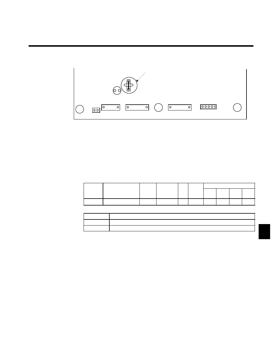
When supplying a voltage input to the frequency reference current input (terminal 39) (a setting of 0
or 1), be sure to disconnect jumper wire J1 on the control board. (See Figure 7.10.) If the jumper wire
isn’t disconnected, the input resistor will be destroyed.
TB3
1CN
9CN
10CN
TB2
L1
J1
Jumper wire
Fig 7.10
Jumper Wire Mounting Location on Control Board
J
Speed Limit Function Settings: d5-03, H3-01, d5-04, d5-05
D
This setting selects the speed limit function used when torque control is performed.
With torque control, the motor sometimes rotates at high speed with no load or a light load. The speed
limit function keeps the motor speed from exceeding the specified limit in these cases.
D
If the speed limit is exceeded during torque control operation, a suppressing torque (proportional to the
divergence from the speed limit) is added to the torque reference. (The suppressing torque is applied
opposite to the motor rotation.)
D
There are two ways to set the motor speed limit: a constant setting or an analog input value.
Speed Limit Selection: d5-03
User
Change
during
Setting
Factory
Valid Access Levels
User
Constant
Number
Name
g
during
Opera-
tion
Setting
Range
Unit Factory
Setting
V/f
Control
V/f with
PG
Open
Loop
Vector
Flux
Vector
d5-03
Speed limit selection
x
1, 2
--
1
x
x
x
A
D
Settings
Setting
Function
1
The speed limit is set from one of the analog frequency reference terminals (36 or 39).
2
The speed limit is set to the value in constant d5-04.
Speed Limit Selection Settings: d5-03, H3-01, d5-04
D
Limit with Analog Input (d5-03 = 1)
•
The speed limit value is set by the input voltage (H3-01) to frequency reference (voltage) terminal
36.
•
When frequency reference (current) terminal 39 has been set to frequency reference by setting
constant H3-09 to 1F, this terminal is also used as an input terminal for the speed limit.
In this case, the actual speed limit value is the sum of the voltage input value at terminal 13 and the
current input value at terminal 39.
•
The polarity of the speed limit signal and the direction of the run command determine the direction
in which the speed is limited.
•
+Voltage input: Forward rotation; Speed is limited in the forward direction.
Reverse rotation; Speed is limited in the reverse direction.
•
--Voltage input: Forward rotation; Speed is limited in the reverse direction.
Reverse rotation; Speed is limited in the forward direction.
•
The speed limit value is zero for rotation opposite to the speed limit direction.
For example, when a +voltage is being input and the forward rotation command is ON, the effective
range of the torque control is from zero to the speed limit value in the forward direction (when
constant d5-05, the speed limit bias, is set to 0).
7