Yaskawa G5HHP Drive User Manual
Page 188
Advanced Operation
7.3.3 Torque Control
7 - 24
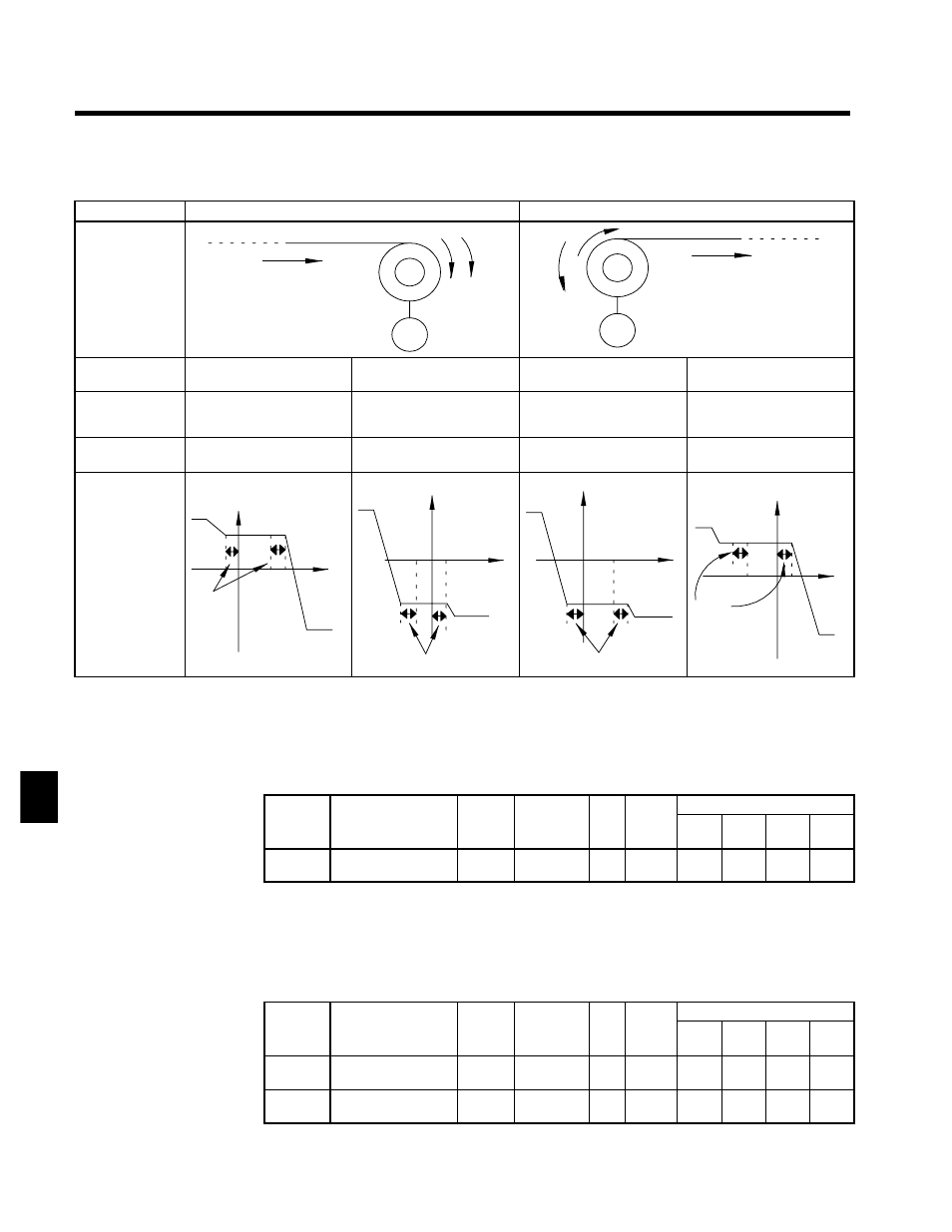
The relationships between the torque reference, speed limits, and motor speed are shown in the following
diagram.
--
Winding Operation
Rewinding Operation
Configuration
Line direction
Motor
N T
X
M
Line direction
N
T
X
M
Normal Rotation
Direction
Forward
Reverse
Forward
Reverse
Torque
Reference
Polarity (TREF)
¨
©
©
¨
Speed Limit
Polarity (SLIM)
¨
©
¨
©
Generated Torque
Torque
limit
TREF
d5
-
05
0 NLIM Speed
Torque
Torque
limit
TREF
d5
-
05
0
NLI
M
Speed
Torque
limit
Torque
limit
Torque
d5
-
05
0
NLIM
Speed
Torque
limit
Torque
limit
Torque
TREF
d5
-
05
0
NLIM
Speed
Torque
limit
Torque
limit
Torque
J
Torque Reference Adjustment: d5-02, H3-02 to H3-11
Primary Delay Time Constant for Torque Reference Filter: d5-02
D
The time constant of the primary filter in the torque reference section can be adjusted.
D
This constant is used to eliminate noise in the torque reference signal and adjust the responsiveness to
the host controller.
User
Change
during
Setting
Factory
Valid Access Levels
User
Constant
Number
Name
g
during
Opera-
tion
Setting
Range
Unit Factory
Setting
V/f
Control
V/f with
PG
Open
Loop
Vector
Flux
Vector
d5-02
Torque reference
delay time
x
0 to 1000
ms
0
x
x
x
A
D
Set the torque reference filter primary delay time constant in ms units.
D
Increase the time constant setting if oscillation occurs during torque control operation.
Setting the Torque Compensation Bias: H3-05, -04, -08, -09
D
Set multi-function analog input (terminal 42) or frequency reference current input (terminal 39) to
torque compensation (setting 14). When the amount of torque loss at the load is input to one of these
terminals, it is added to the torque reference to compensate for the loss.
User
Change
during
Setting
Factory
Valid Access Levels
User
Constant
Number
Name
g
during
Opera-
tion
Setting
Range
Unit Factory
Setting
V/f
Control
V/f with
PG
Open
Loop
Vector
Flux
Vector
H3-05
Multi-function analog
input (terminal 42)
x
0 to 1F
--
0
B
B
B
B
H3-09
Multi-function analog
input (terminal 39)
x
1 to 1F
--
1F
A
A
A
A
7