Yaskawa G5HHP Drive User Manual
Page 314
Troubleshooting
9.1.1 Fault Detection
9 - 4
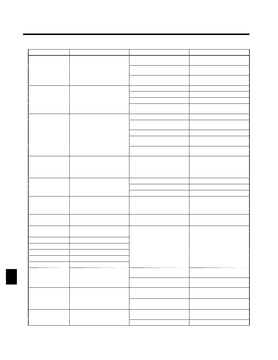
Corrective Actions
Probable Causes
Meaning
Fault Display
Overspeed
The speed has been greater than the
i
i F1 08 f l
h
h
Overshooting/Undershooting are oc-
curring.
Adjust the gain again.
OS
Over speed
The speed has been greater than the
setting in F1-08 for longer than the
setting in F1-09.
The reference speed is too high.
Check the reference circuit and refer-
ence gain.
Over speed
The settings in F1-08 and F1-09 aren’t
appropriate.
Check the settings in F1-08 and F1-09.
PG Disconnection Detected
There is a break in the PG wiring.
Fix the broken/disconnected wiring.
PGO
The PG is disconnected.
The Inverter is outputting a frequency,
The PG is wired incorrectly.
Fix the wiring.
PGO
PG open
The Inverter is outputting a frequency,
but PG pulses aren’t being input.
Power isn’t being supplied to the PG.
Supply power to the PG properly.
PG open
----
Check for open circuit when using
brake (motor).
Excessive Speed Deviation
The load is too heavy.
Reduce the load.
The speed deviation has been greater
than the setting in F1-10 for longer
than the setting in F1-11.
The acceleration time and deceleration
time are too short.
Lengthen the acceleration time and
deceleration time.
DEV
S
d D i i
than the setting in F1-11.
The load is locked.
Check the mechanical system.
Speed Deviation
The settings in F1-10 and F1-11 aren’t
appropriate.
Check the settings in F1-10 and F1-11.
----
Check for open circuit when using
brake (motor).
CF
Out of Control
Control Fault
The torque limit was reached continu-
ously for 3 seconds or longer during a
deceleration stop during open-loop
vector control.
----
Check the motor constants.
SVE
Zero Servo Fault
The torque limit is too small.
Increase the limit.
SVE
Zero Servo Fault
The rotation position moved during
zero servo operation.
The load torque is too large.
Reduce the load torque.
Zero Servo Fault
zero servo operation.
----
Check for signal noise.
OPR
Oper Disconnect
Operator Connection Fault
The Operator was disconnected dur-
ing operation started by a run com-
mand from the Operator.
----
Check the Operator connection.
EFO
Opt External Flt
External fault input from Transmis-
sion Option Card.
----
Check the Trsansmission Option Card
and transmission signal.
EF3
External Fault 3
External fault (Input terminal 11)
EF4
External fault (Input terminal 12)
S
Reset external fault inputs to the
lti f
ti
i
t
EF5
External fault (Input terminal 13)
An “external fault” was input from a
multi-function input.
p
multi-function inputs.
S
Remove the cause of the external
EF6
External fault (Input terminal 14)
multi-function input.
S
Remove the cause of the external
fault.
EF7
External fault (Input terminal 15)
EF8
External fault (Input terminal 16)
CPF00
Operator Communications Error 1
Communications with the Operator
bli h d i hi 5
d
The Digital Operator’s connector isn’t
connected properly.
Disconnect the Digital Operator and
then connect it again.
COM-ERR (OP&INV)
Communications with the Operator
were not established within 5 seconds
after the power was turned on.
The Inverter’s control circuits are
faulty.
Replace the Inverter.
CPF01
Operator Communications Error 2
After communications were estab-
lished there was a transmission error
The Digital Operator isn’t connected
properly.
Disconnect the Digital Operator and
then connect it again.
COM-ERR (OP&INV)
lished, there was a transmission error
with the Digital Operator for more
than 2 seconds.
The Inverter’s control circuits are
faulty.
Replace the Inverter.
CPF02
BB Circuit Err
Baseblock circuit error
----
Try turning the power supply off and
on again.
BB Circuit Err
The control circuit is damaged.
Replace the Inverter.
9