Stall prevention: l3 – Yaskawa G5HHP Drive User Manual
Page 301
8.2 Programming Mode Constants
8 - 35
J
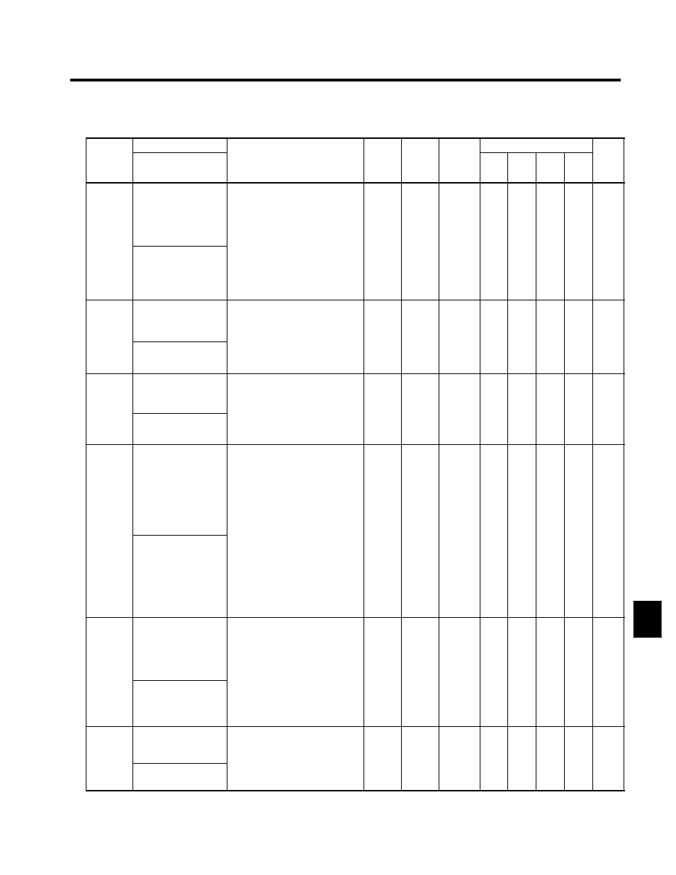
Stall Prevention: L3
C
t t
Name
S tti
F t
Change
Control Methods
Constant
Number
Display
Description
Setting
Range
Factory
Setting
Change
during
Opera-
tion
V/f
V/f
with
PG
Open
Loop
Vector
Flux
Vector
Page
L3-01
Stall prevention
selection during accel
0: Disabled (Acceleration as set.
With a heavy load, the motor
may stall.)
1: Enabled (Acceleration stopped
when L3-02 level is exceeded.
Acceleration starts again when
the current is returned )
0 to 2
1
x
B
B
B
x
7 - 88
L3 01
StallP Accel Sel
the current is returned.)
2: Intelligent acceleration mode
(Using the L3-02 level as a ba-
sis, acceleration is automatically
adjusted. Set acceleration time
is disregarded.)
0 to 2
1
x
B
B
B
x
7 - 88
L3-02
Stall prevention level
during accel
Effective when L3-01 is set to 1 or
2.
Set as a percentage of Inverter rated
current.
0 to 200
150
x
B
B
B
x
7 - 88
L3 02
StallP Accel Lvl
current.
;
Usually setting is not necessary.
The factory setting reduces the
set values when the motor stalls.
0 to 200
150
x
B
B
B
x
7 - 88
L3-03
Stall prevention limit
during accel
Sets the lower limit for stall preven-
tion during acceleration, as a per-
centage of the Inverter rated cur-
rent, when operation is in the fre-
b
th
i
0 to 100
50
x
A
A
A
x
7 - 89
L3 03
StallP CHP Lvl
,
p
quency range above the maximum
voltage frequency (E1-06.)
;
Usually setting is not necessary.
0 to 100
50
x
A
A
A
x
7 - 89
L3-04
Stall prevention
selection during decel
0: Disabled (Deceleration as set. If
deceleration time is too short, a
main circuit overvoltage may
result.)
1: Enabled (Deceleration is
stopped when the main circuit
voltage exceeds the overvoltage
level. Deceleration restarts
when voltage is returned.)
2 I t lli
t d
l
ti
d
0 to 2
1
x
B
B
B
B
7 - 90
L3 04
StallP Decel Sel
2: Intelligent deceleration mode
(Deceleration rate is automati-
cally adjusted so that in Inverter
can decelerate in the shortest
possible time. Set deceleration
time is disregarded.)
;
When a braking option (Braking
Resistor Unit or Braking Unit) is
used, always set to 0 (Disabled.)
0 to 2
1
x
B
B
B
B
7 - 90
L3-05
Stall prevention
selection during run-
ning
0: Disabled (Runs as set. With a
heavy load, the motor may
stall.)
1: Enabled: Deceleration time 1
(the deceleration time for the
stall prevention function is
C1-02 )
0 to 2
1
x
B
B
x
x
7 - 90
StallP Run Sel
C1-02.)
2: Enabled: Deceleration time 2
(the deceleration time for the
stall prevention function is
C1-04.)
L3-06
Stall prevention level
during running
Effective when L3-04 is 1 or 2.
Set as a percentage of the Inverter
rated current.
;
U
ll
i
i
30 to
200
160
x
B
B
x
x
7 - 90
L3 06
StallP Run Level
;
Usually setting is not necessary.
The factory setting reduces the
set values when the motor stalls.
200
160
x
B
B
x
x
7 - 90
8