Yaskawa G5HHP Drive User Manual
Page 83
4.2 Modes
4 - 15
Func-
tion
Valid Access Levels
Min.
Unit
Output Signal Levels for
Multi-function Analog
Outputs
Function
Name
Con-
stant
No.
Func-
tion
Flux
Vec-
tor
Open
-loop
Vec-
tor
V/f w/
PG
V/f
Min.
Unit
Output Signal Levels for
Multi-function Analog
Outputs
Function
Digital Operator
Display
Con-
stant
No.
U1-12
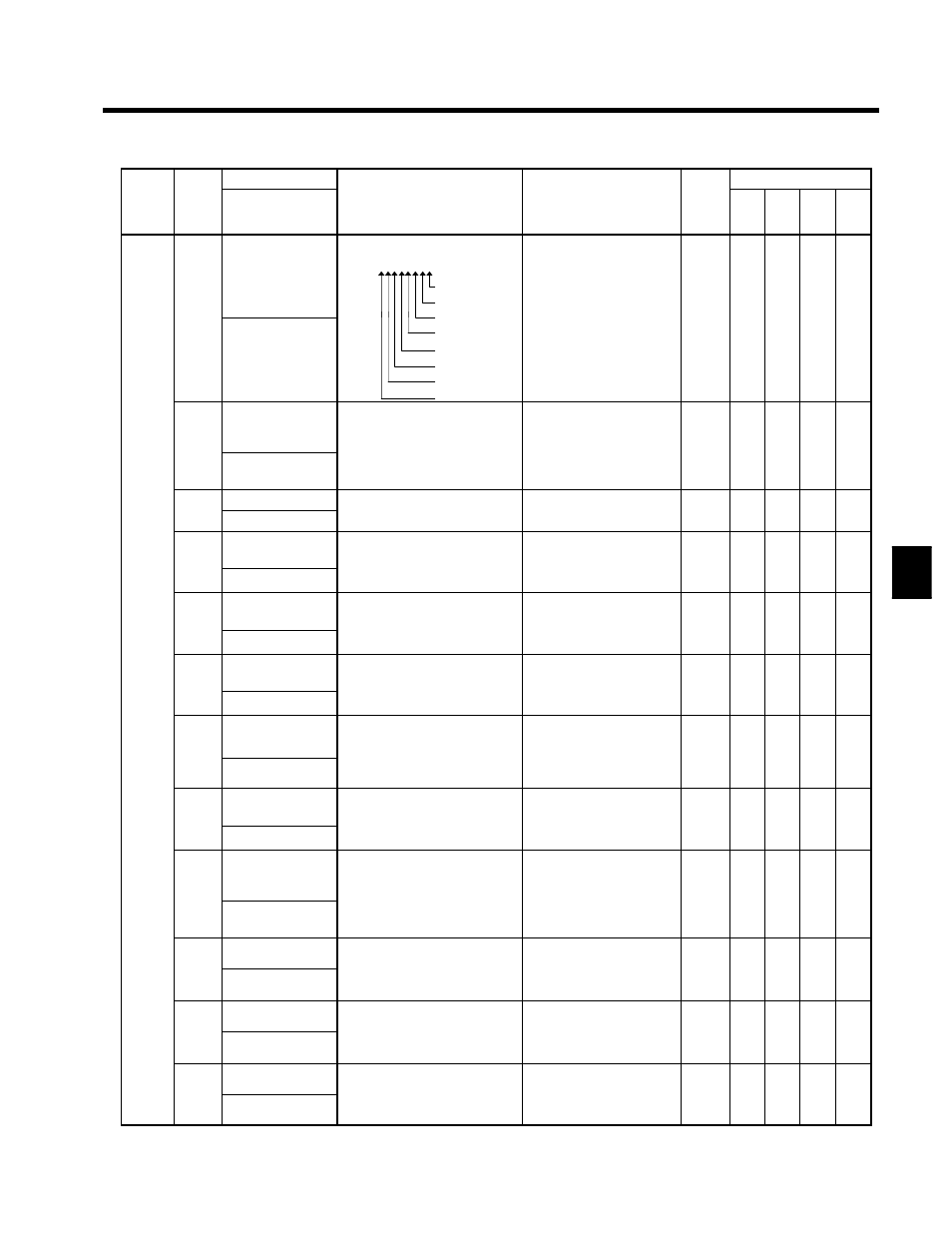
Operation status
Inverter operating status.
U1-12 = 0 0 0 0 0 0 0 0
1: Running
1: Zero-speed level
1: Reverse
Can’t be output
Q
Q
Q
Q
U1-12
Int Ctl Sts 1
1: Reverse
1: Reset input ON
1: F.ref/F.out agree
1: Inverter ready
1: Minor fault detected
1: Major fault detected
Can’t be output.
--
Q
Q
Q
Q
U1-13
Cumulative opera-
tion time
Monitors the Inverter’s elapsed
operating time.
The initial value and running/
power on time selection can be set Can’t be output.
1 hr
Q
Q
Q
Q
U1 13
Elapsed Time
g
power-on time selection can be set
with user constants o2-07 and
o2-08.
Can t be output.
1 hr
Q
Q
Q
Q
U1-14
Software No.
Manufacturer’s ID number
Can’t be output
Q
Q
Q
Q
U1-14
FLASH ID
Manufacturer’s ID number
Can’t be output.
--
Q
Q
Q
Q
U1-15
Terminal 13 input
voltage level
Monitors the input voltage of the
frequency reference (voltage).
An inp t of 10 V corr sponds to
10 V: 100% (10 V)
(0 to ±10 V possible)
0.1 %
B
B
B
B
U1 15
Term 13 Level
An input of 10 V corresponds to
100%.
(0 to ±10 V possible)
0.1 %
B
B
B
B
U1-16
Terminal 14 input
current level
Monitors the input current of the
frequency reference (current).
An inp t of 20 mA corr sponds to
20 mA: 100% (20 mA)
(0 to +10 V output)
0.1 %
B
B
B
B
U1 16
Term 14 Level
An input of 20 mA corresponds to
100%.
(0 to +10 V output)
0.1 %
B
B
B
B
Status
Moni-
tor
U1-17
Terminal 16 input
voltage level
Monitors the input voltage of the
multi-function analog input.
An inp t of 10 V corr sponds to
10 V: 100% (10 V)
(0 to ±10 V possible)
0.1 %
B
B
B
B
tor
U1 17
Term 16 Level
An input of 10 V corresponds to
100%.
(0 to ±10 V possible)
0.1 %
B
B
B
B
U1-18
Motor secondary
current (lq)
Monitors the calculated value of
the motor’s secondary current
(Iq).
10 V: Rated secondary cur-
rent
0.1 %
B
B
B
B
U1 18
Mot SEC Current
(Iq).
The motor’s rated secondary cur-
rent corresponds to 100%.
rent
(0 to +10 V output)
0.1 %
B
B
B
B
U1-19
Motor exciting cur-
rent (ld)
Monitors the calculated value of
the motor’s excitation current (Id).
Th motor’s r t d s cond r c r
10 V: Rated secondary cur-
rent
0.1 %
X
X
B
B
U1 19
Mot EXC Current
The motor’s rated secondary cur-
rent corresponds to 100%.
e t
(0 to +10 V output)
0.1 %
X
X
B
B
U1-20
Output frequency
after soft-start
Monitors the output frequency af-
ter a soft start.
The display shows the frequency
without the correction from com
10 V: Max. frequency
(0 to ±10 V possible)
0.01
Hz
A
A
A
A
U1 20
SFS Output
p y
q
y
without the correction from com-
pensation functions such as slip
compensation.
(0 to ±10 V possible)
Hz
A
A
A
A
U1-21
ASR input
Monitors the input to the speed
control loop.
10 V: Max. frequency
0 01 %
X
A
X
A
U1-21
ASR Input
co t o oop.
The max. frequency corresponds
to 100%.
10 V: Max. frequency
(0 to ±10 V possible)
0.01 %
X
A
X
A
U1-22
ASR output
Monitors the output from the
speed control loop.
10 V: Rated secondary cur-
rent
0 01 %
X
A
X
A
U1-22
ASR Output
speed control loop.
The motor’s rated secondary cur-
rent corresponds to 100%.
rent
(0 to ±10 V possible)
0.01 %
X
A
X
A
U1-23
Speed deviation
Monitors the speed deviation
within the speed control loop.
10 V: Max. frequency
0 01 %
X
A
X
A
U1-23
Speed Deviation
w t
t e speed co t o oop.
The max. frequency corresponds
to 100%.
10 V: Max. frequency
(0 to ±10 V possible)
0.01 %
X
A
X
A
4