Pg-x2 (for flux vector control mode only) – Yaskawa G5HHP Drive User Manual
Page 56
Wiring
3.7.2 PG Speed Control Card Terminal Blocks
3 - 16
Note 5 VDC and 12 VDC cannot be used at the same time.
J
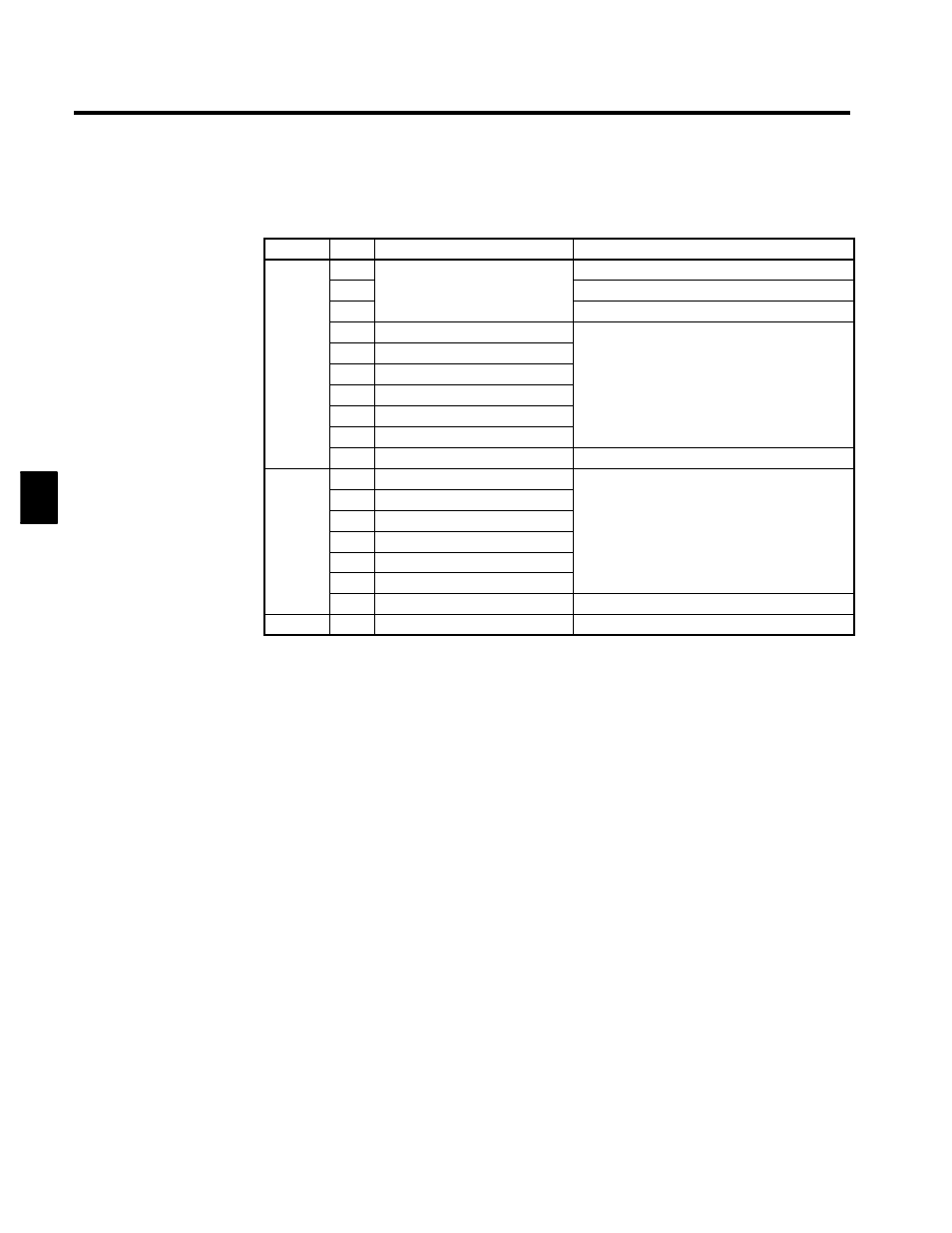
PG-X2 (For Flux Vector Control Mode Only)
Table 3.6 PG-X2 Terminal Specifications
Terminal
No.
Contents
Specifications
1
12 VDC (±5%), 200 mA max. (see note)
2
Power supply for pulse generator
0 VDC (GND for power supply)
3
pp y
p
g
5 VDC (±5%), 200 mA max. (see note)
4
A-phase + input terminal
TA1
5
A-phase -- input terminal
TA1
6
B-phase + input terminal
Line driver input (RS-422 level input)
7
B-phase -- input terminal
Line driver input (RS-422 level input)
Maximum response frequency: 300 kHz
8
Z-phase + input terminal
9
Z-phase -- input terminal
10
Common terminal
0 VDC (GND for power supply)
1
A-phase + output terminal
2
A-phase -- output terminal
3
B-phase + output terminal
Line driver output (RS 422 level output)
TA2
4
B-phase -- output terminal
Line driver output (RS-422 level output)
5
Z-phase + output terminal
6
Z-phase -- output terminal
7
Control circuit common
Control circuit GND
TA3
(E)
Shield connection terminal
--
Note 5 VDC and 12 VDC cannot be used at the same time.
3