7 installing and wiring pg speed control cards, 1 installing a pg speed control card – Yaskawa G5HHP Drive User Manual
Page 54
Wiring
3.7.1 Installing a PG Speed Control Card
3 - 14
3.7 Installing and Wiring PG Speed Control Cards
PG Speed Control Cards are used for executing speed control using a pulse generator (PG). There are four types
of PG speed control, as shown below. Select the type that fits the application and control method.
PG-A2
A-phase (single) pulse input for open collector output or complementary outputs, for V/f control
PG-B2
A/B-phase pulse input for open collector output or complementary outputs, for vector control
PG-D2
A-phase (single) pulse input for line driver input, for V/f control
PG-X2
A/B/Z-phase pulse input for line driver input, for vector control
3.7.1 Installing a PG Speed Control Card
Use the following procedure to install a PG Speed Control Card.
1. Turn OFF the main-circuit power supply of the Inverter Panel.
2. Leave it OFF for at least five minutes before opening the front door of the Inverter Panel. Check to be
sure that the CHARGE lamp is OFF.
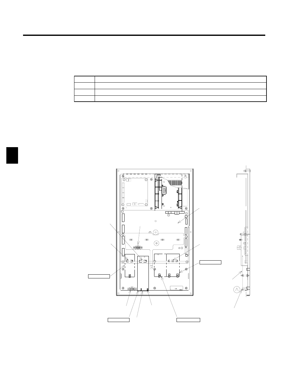
3. After aligning to the Option-A connector on the control PCB located on the back of the front panel of
the Inverter Panel, pass the spacer through the spacer hole at the Card. (Refer to A in the illustration.)
Check to be sure that it is precisely aligned with the 4CN position, and snap it into the proper position.
Be sure to press it in firmly until you hear it snap into place.
Ground terminal
Option A
Option CD
Option C
Control
board
Option D
4CN
Option-A
Connector
2CN
Option-C
Connector
3CN
Option-D
Connector
Spacer
[Front]
[Side]
PG Speed
Control
Card
Spacer
PG Speed
Control
Card
Top
Bottom
Fig 3.8
Installing a PG Speed Control Card
3