Droop control: b7, Energy saving: b8, Zero servo: b9 – Yaskawa G5HHP Drive User Manual
Page 274
User Constants
8.2.1 Application Constants: b
8 - 8
J
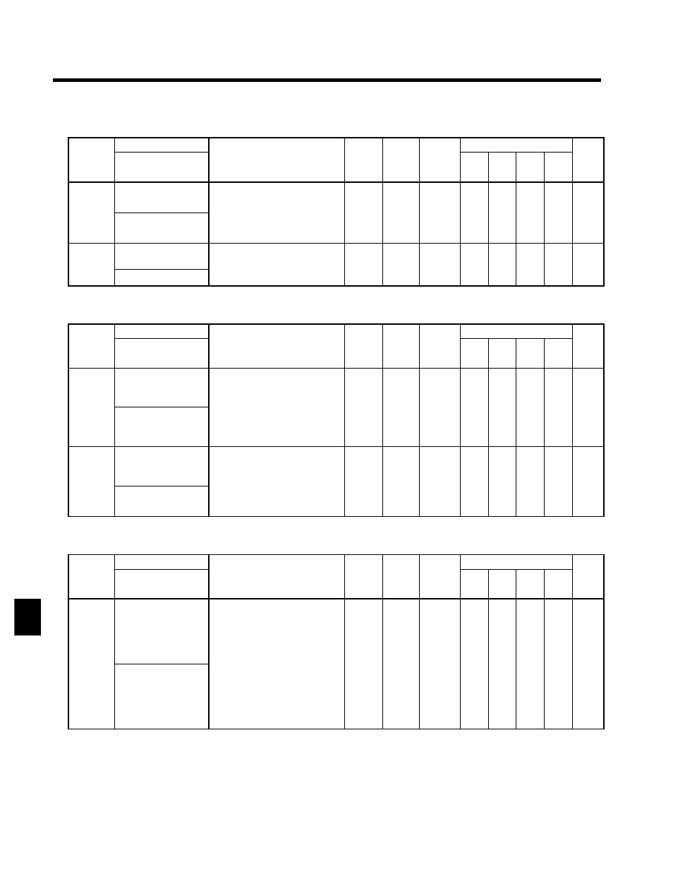
Droop Control: b7
C
t t
Name
S tti
F t
Change
Control Methods
Constant
Number
Display
Description
Setting
Range
Factory
Setting
Change
during
Opera-
tion
V/f
V/f
with
PG
Open
Loop
Vector
Flux
Vector
Page
b7-01
Droop control gain
Sets the slip as a percentage of
maximum frequency when the
maximum output frequency is spe-
ifi d
d h
d
0.0 to
0 0
f
x
x
x
A
7 17
b7-01
Droop Gain
maximum output frequency is spe
cified and the rated torque occurs.
;
Droop-control is not performed
when the setting is 0.0.
0.0 to
100.0
0.0
f
x
x
x
A
7 - 17
b7-02
Droop control delay
time
Droop control responsiveness
constant
;
Wh
h ti
ill ti
0.03 to
2 00
0.05
f
x
x
x
A
7 - 17
b7 02
Droop Delay Time
;
When hunting or oscillation oc-
curs, increase the value.
2.00
0.05
f
x
x
x
A
7 - 17
J
Energy Saving: b8
C
t t
Name
S tti
F t
Change
Control Methods
Constant
Number
Display
Description
Setting
Range
Factory
Setting
Change
during
Opera-
tion
V/f
V/f
with
PG
Open
Loop
Vector
Flux
Vector
Page
b8-01
Energy-saving gain
Sets the Inverter output voltage
when the energy-saving command
is input.
;
Enabled when the “energy-sav-
0 to 100
80
x
A
A
x
x
7 - 12
b8-01
Energy Save Gain
;
Enabled when the “energy-sav-
ing mode” command is set for
multi-function input. Set as a
percentage of the V/f pattern
voltage.
0 to 100
80
x
A
A
x
x
7 12
7 - 35
b8-02
Energy-saving fre-
quency
Sets the energy-saving effective
range minimum frequency in Hz.
;
The energy-saving function is
only enabled when the frequency
0.0 to
150 0
0.0
x
A
A
x
x
7 - 12
7 35
b8 02
Energy Save Freq
only enabled when the frequency
is greater than the energy-saving
frequency and the speeds are
consistent.
150.0
0.0
x
A
A
x
x
7 - 35
J
Zero Servo: b9
C
t t
Name
S tti
F t
Change
Control Methods
Constant
Number
Display
Description
Setting
Range
Factory
Setting
Change
during
Opera-
tion
V/f
V/f
with
PG
Open
Loop
Vector
Flux
Vector
Page
b9-01
Zero-servo gain
Used to adjust the strength of the
zero-servo lock.
;
Enabled when the “zero-servo
command” is set for the multi-
function input. When the zero-
servo command has been input
and the frequency reference
0 to 100
5
x
x
x
x
A
7 18
b9-01
Zero Servo Gain
and the frequency reference
drops below excitation level
(b2-01), a position control loop
is created and the motor stops.
Increasing the zero-servo gain in
turn increases the strength of the
lock. Increasing it by too much
will cause oscillation.
0 to 100
5
x
x
x
x
A
7 - 18
8