4 option constants: f, Installing option cards – Yaskawa G5HHP Drive User Manual
Page 220
Advanced Operation
7.5.4 Option Constants: F
7 - 56
7.5.4 Option Constants: F
J
Installing Option Cards
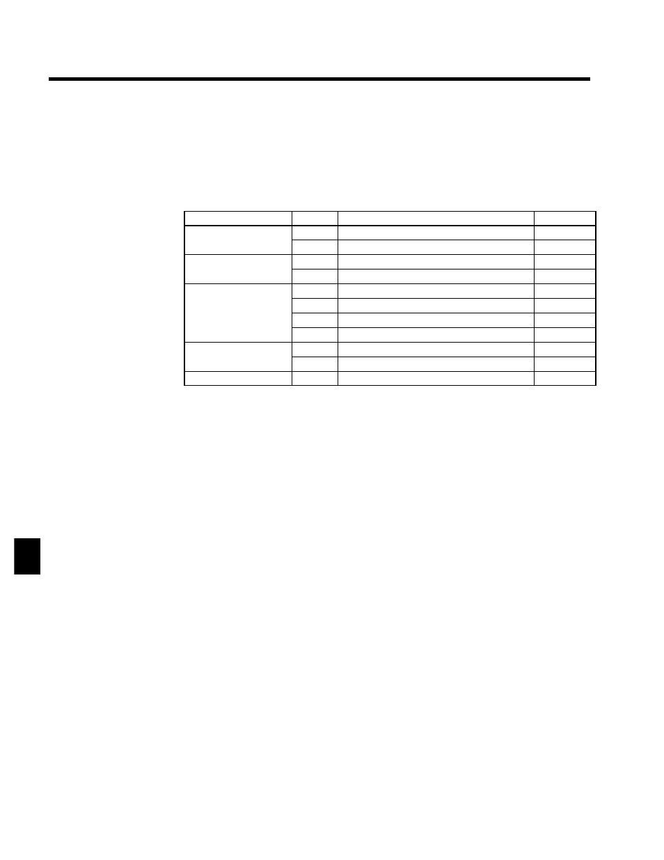
A maximum of three Option Cards can be installed in the Inverter. The installation location of each is deter-
mined by the type of Card. Be sure to install the Cards in their correct locations.
Constants of the Option Cards can be referred or set with the access level Basic.
Table 7.7 Option Card Specifications
Type of card
Model
Specifications
Location
Analog Reference Card
AI-14U
14-bit analog, 2 inputs (voltage/current)
C
Analog Reference Card
AI-14B
14-bits analog, 3 inputs
C
Digital Reference Card
DI-08
8-bit digital input (BCD/binary)
C
Digital Reference Card
DI-16H2
16-bit digital input (BCD/binary)
C
PG-A2
Open-collector/complementary, single input
A
PG Speed Control Card
PG-B2
Complementary, A/B-phase input
A
PG Speed Control Card
PG-D2
Line-driver, single input
A
PG-X2
Line-driver, A/B-phase input
A
Analog Monitor Card
AO-08
8-bit analog output, 2 channels
D
Analog Monitor Card
AO-12
12-bit analog output, 2 channels
D
Pulse Monitor Card
PO-36F
Pulse frequency output
D
Installation Procedure
Use the following procedure to install a PG Speed Control Card.
1. Turn OFF the main-circuit power supply of the Inverter Panel.
2. Leave it OFF for at least five minutes before opening the front panel of the Inverter Panel. Check to be
sure that the CHARGE lamp is OFF.
7