Yaskawa G5HHP Drive User Manual
Page 233
7.5 Common Functions
7 - 69
Operation
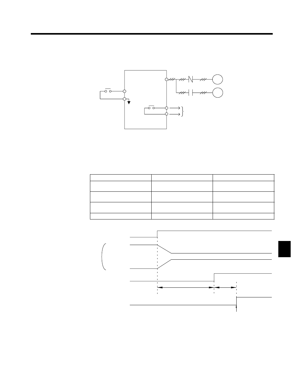
Motor Switch command
(CLOSED for motor 2)
U, V, W
(T1, T2, T3)
Multi-function input
Multi-function output
Note Use an external sequence to switch between M1 and M2
and to confirm the motor selection status.
M1
M2
IM
Motor 1 (main motor)
Motor 2 (auxiliary motor)
Motor selection monitor
(CLOSED for motor 2)
IM
•
The control method, V/f characteristics, and motor constants recorded in the Inverter can be
switched by setting “16” (motor switch command) for a constant from H1-01 to 06 (multi-function
inputs), and then inputting a signal while the motor is stopped.
•
The current motor selection can be monitored at a multi-function output terminal by setting “1C”
(motor selection monitor) for a constant from H2-01 to 03 (multi-function outputs).
•
Set the Basic (3) or Advanced (4) access level in the initialize setting A1-01 (access level).
•
The constants being used will changed as shown in the following table for the motor switch com-
mand.
Motor Switch command
OPEN (motor 1)
CLOSED (motor 2)
Control method
A1-02 (control method in initialize
settings)
E3-01 (motor 2 control method)
V/f characteristics
E1-04 to 13 (V/f characteristics)
E4-01 to 07 (motor 2 V/f character-
istics)
Motor constants
E2-01 to 09 (motor constants)
E5-01 to 06 (motor 2 motor
constants)
Motor selection monitor
OPEN
CLOSED
D
The timing chart for switching between motor 1 and motor 2 is shown below.
Turn ON the Forward (reverse) command only
after confirming the status of the motor selection
monitor.
Motor switching
contactor
Motor switch command
M1 operation
M2 operation
Motor selection monitor
Forward (reverse)
command
OFF
ON
Approx. 200 ms
Approx.
50 ms
OFF
ON
OFF
ON
OFF
ON
OFF
ON
(Approx. 500 ms for control with a PG)
Fig 7.33
Timing Chart for Switching from Motor 1 to Motor 2
7