Yaskawa G5HHP Drive User Manual
Page 243
7.5 Common Functions
7 - 79
Zero-servo End (Setting: 33)
OFF
The zero-servo command isn’t being input or zero-servo position control hasn’t been completed.
ON
The position has been brought within the zero servo completion width (b9-02) after the zero-ser-
vo command was input.
D
This output function indicates that zero-servo position control has been completed.
D
The output is turned ON after the zero-servo command is input and the difference between the zero-ser-
vo operation starting position and the current position is within the zero servo completion width (b9-02).
J
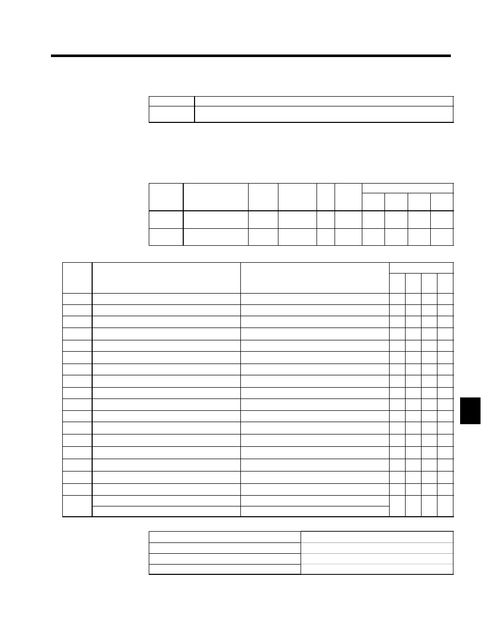
Multi-function Analog Input/Frequency Reference (Current): H3-05, H3-09
Constant Settings
User
Change
during
Setting
Factory
Valid Access Levels
User
Constant
Number
Name
g
during
Opera-
tion
Setting
Range
Unit Factory
Setting
V/f
Control
V/f with
PG
Open
Loop
Vector
Flux
Vector
H3-05
Multi-function analog
input (terminal 42)
x
0 to 1F
--
0
B
B
B
B
H3-09
Multi-function analog
input (terminal 39)
x
0 to 1F
--
1F
A
A
A
A
Table 7.11 Multi-function Input/Frequency Reference (Voltage) Function
Control Method
Setting
Function
Equivalent of 100% Input (10 V or 20 mA)
V/f
V/f
w/
PG
Open
-loop
Vec-
tor
Flux
Vec-
tor
0
Auxiliary frequency reference (H3-05)
Maximum output frequency
f
f
f
f
1
Frequency gain
Frequency reference (voltage) command value
f
f
f
f
2
Frequency bias
Maximum output frequency (added to H3-03)
f
f
f
f
4
Voltage bias
Motor rated voltage (E1-05)
f
f
x
x
5
Accel/Decel change (reduction coefficient)
Accel/Decel times (C1-01 to C1-08)
f
f
f
f
6
DC injection braking current
Inverter rated output current
f
f
f
x
7
Overtorque detection level
Motor rated torque
f
f
f
f
8
Stall prevention level during run
Inverter rated output current
f
f
x
x
9
Frequency reference lower limit level
Maximum output frequency
f
f
f
f
A
Jump frequency
Maximum output frequency
f
f
f
f
B
PID feedback
Maximum output frequency
f
f
f
f
10
Forward side torque limit
Motor rated torque
x
x
f
f
11
Reverse side torque limit
Motor rated torque
x
x
f
f
12
Regeneration for torque limit
Motor rated torque
x
x
f
f
13
Torque reference/torque limit for speed control
Motor rated torque
x
x
x
f
14
Torque compensation bias
Motor rated torque
x
x
x
f
15
Forward/reverse torque limit
Motor rated torque
x
x
f
f
1F
Disable analog input (H3-05)
----
f
f
f
f
1F
Frequency Reference (H3-09)
Maximum output frequency
f
f
f
f
D
The analog input signal level, gain, and bias are set with the following constants.
Terminal 42 signal level selector
H3-04 (0 to +10 V or 0 to ±10 V)
Terminal 42 input gain
H3-06
Terminal 42 input bias
H3-07
Terminal 39 signal level selector
H3-08 (0 to +10 V, 0 to ±10 V, or 4 to 20 mA)
7