Yaskawa G5HHP Drive User Manual
Page 172
Advanced Operation
7.1.3 Setting/Adjusting Motor Constants
7 - 8
Adjusting Output Voltage: VC (E1-08), VMIN (E1-10)
Adjust the output voltage when you want to output more torque at low speed, such as in an elevator, or when
torque isn’t really necessary and you want to reduce the output voltage to save energy.
Adjustment range:
400-V class Inverters: Initial value
±
0 to 2 V
575-V class Inverters: Initial value
±
0 to 4 V
D
When generating more torque, gradually increase the voltage but do not exceed 100% of the motor’s
rated current.
D
When saving energy, decrease the voltage but do not cause stalling.
Setting the Maximum Output Frequency
The maximum output frequency can be set from 50.0 to 150.0 Hz. Set this constant in accordance with the
motor’s maximum rotational speed.
J
Setting Motor Constants: E2-01 through E2-03 (E5-01 through E5-03), E2-05
through E2-08 (E5-05, E5-06)
D
The motor constants (function E2) will all be set automatically when autotuning is performed, so it nor-
mally isn’t necessary to set them manually. Set these constants manually if autotuning can’t be com-
pleted properly.
D
User constant numbers for motor 2 are given in parentheses.
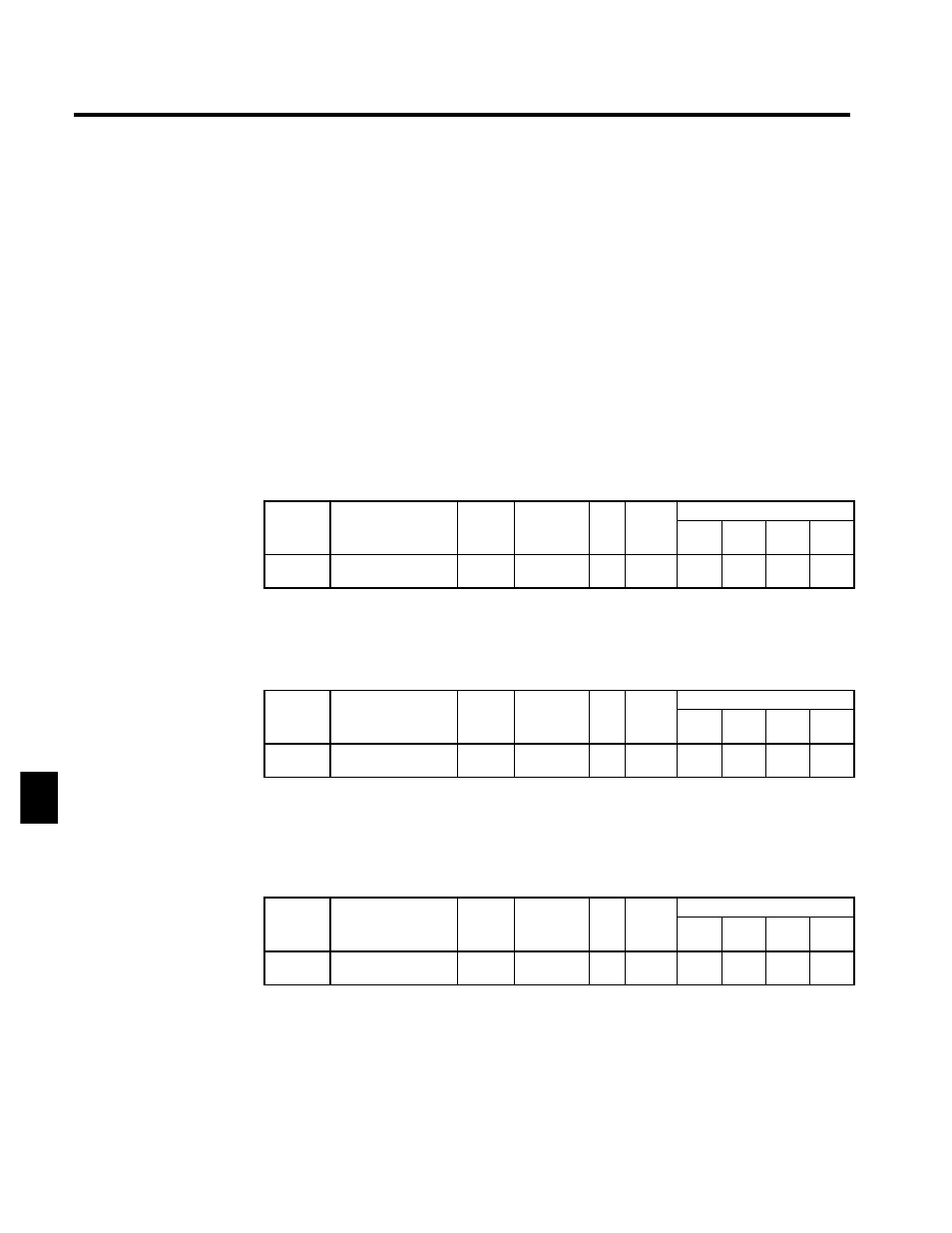
Motor Rated Current: E2-01
User
Change
during
Setting
Factory
Valid Access Levels
User
Constant
Number
Name
g
during
Opera-
tion
Setting
Range
Unit Factory
Setting
V/f
Control
V/f with
PG
Open
Loop
Vector
Flux
Vector
E2-01
(E5-01)
Motor rated current
x
37.0 to
740.0
A
370.0
Q
Q
Q
Q
D
The setting range is 10% to 200% of the Inverter rated output current. The default setting depends upon
the Inverter capacity. (The table shows the default setting for 400-V class, 200 kW Inverters.) (See page
8 - 42.)
D
Set the rated current (A) shown on the motor nameplate.
Motor Rated Slip: E2-02
User
Change
during
Setting
Factory
Valid Access Levels
User
Constant
Number
Name
g
during
Opera-
tion
Setting
Range
Unit Factory
Setting
V/f
Control
V/f with
PG
Open
Loop
Vector
Flux
Vector
E2-02
(E5-02)
Motor rated slip
x
0.00 to
20.00
Hz
1.30
A
A
Q
Q
D
The default setting depends upon the Inverter capacity.
(The table shows the default settings for 400-V class, 200 kW Inverters.)
D
Calculate the rated slip (E2-02) from the value shown on the motor nameplate with the following equa-
tion and set this value.
Rated slip = rated frequency (Hz) -- rated speed (r/min) × number of poles/120
Motor No-load Current: E2-03
User
Change
during
Setting
Factory
Valid Access Levels
User
Constant
Number
Name
g
during
Opera-
tion
Setting
Range
Unit Factory
Setting
V/f
Control
V/f with
PG
Open
Loop
Vector
Flux
Vector
E2-03
(E5-03)
Motor no-load current
x
0.00 to
2000.0
A
96.0
A
A
Q
Q
D
The default setting depends upon the Inverter capacity.
(The table shows the default settings for 400-V class, 200 kW Inverters.)
D
Set the no-load current (E2-03) at the rated voltage and rated frequency. Normally this value isn’t shown
on the motor nameplate, so it might be necessary to contact the motor manufacturer.
7