Yaskawa G5HHP Drive User Manual
Page 265
7.5 Common Functions
7 - 101
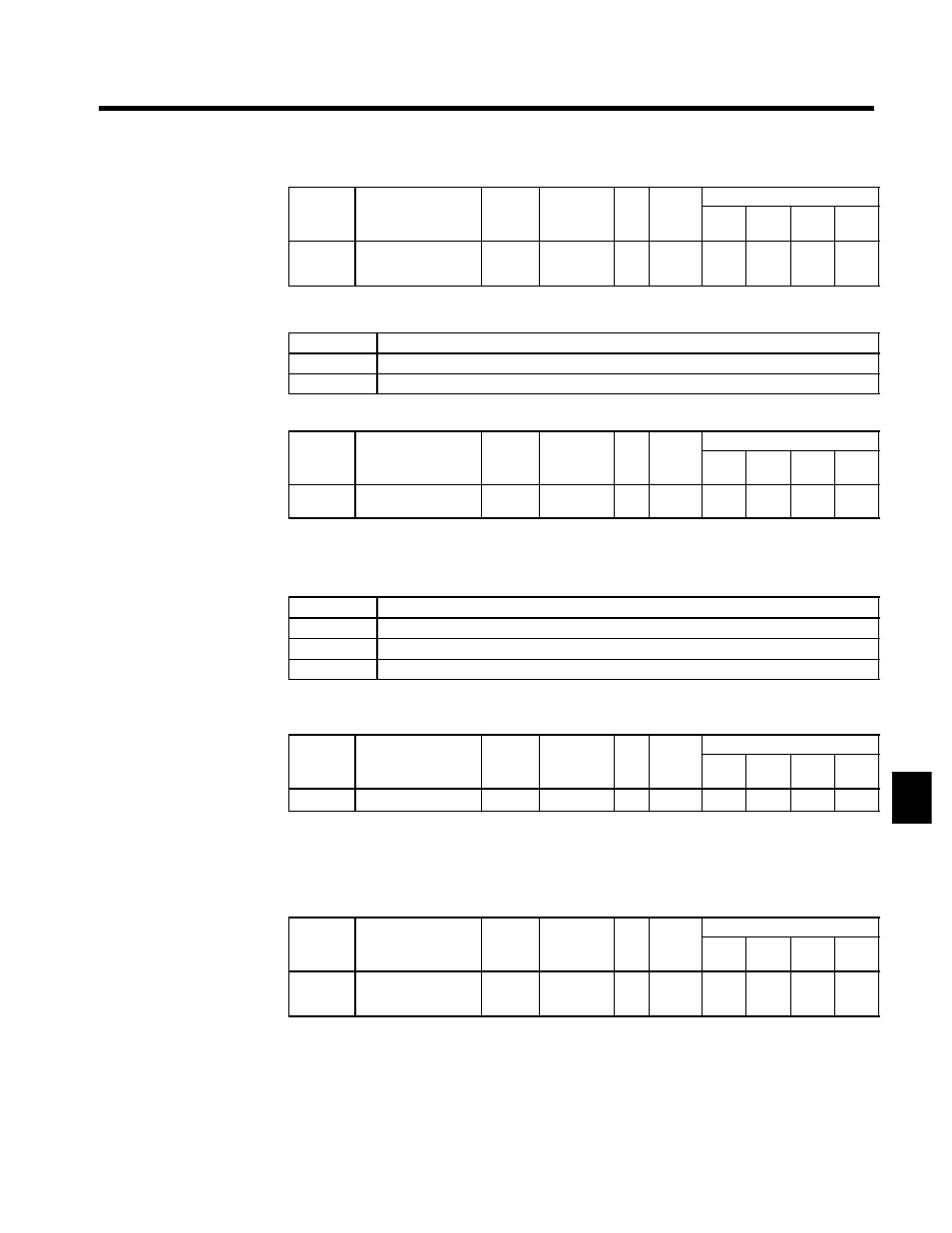
STOP Key During Control Circuit Terminal Operation: o2-02
User
Change
during
Setting
Factory
Valid Access Levels
User
Constant
Number
Name
g
during
Opera-
tion
Setting
Range
Unit Factory
Setting
V/f
Control
V/f with
PG
Open
Loop
Vector
Flux
Vector
o2-02
STOP Key during
control circuit termi-
nal operation
x
0, 1
--
1
B
B
B
B
D
This constant enables or disables the STOP on the Digital Operator
D
Settings
Setting
Function
0
Disabled. (The STOP Key is disabled when the run command is input from an external terminal.)
1
Enabled. (The STOP Key is enabled at all times during operation.)
User Constant Initial Value: o2-03
User
Change
during
Setting
Factory
Valid Access Levels
User
Constant
Number
Name
g
during
Opera-
tion
Setting
Range
Unit Factory
Setting
V/f
Control
V/f with
PG
Open
Loop
Vector
Flux
Vector
o2-03
User constant initial
value
x
0 to 2
--
0
B
B
B
B
D
This constant is used to record or clear the user constant defaults.
D
Once the user defaults have been recorded, constant A1-03 can be used to initialize the Inverter
constants to these defaults.
D
Settings
Setting
Function
0
No change. (Retain current settings.)
1
Record user defaults. (Record the current constant settings as user defaults.)
2
Clear user defaults. (Clear the recorded user defaults.)
D
The Digital Operation display will return to 0 after the settings have been made.
kVA Selection: o2-04
User
Change
during
Setting
Factory
Valid Access Levels
User
Constant
Number
Name
g
during
Opera-
tion
Setting
Range
Unit Factory
Setting
V/f
Control
V/f with
PG
Open
Loop
Vector
Flux
Vector
o2-04
kVA selection
x
0 to FF
--
0
B
B
B
B
D
The setting range and factory setting depend on the Inverter capacity. The settings shown in the table
are for a 400-V class, 200 kW Inverter. (See page 8 - 42.)
D
Do not change this constant setting; it is used by the manufacturer to identify the Inverter model.
D
Use this setting only the the control PC board has been replaced.
Frequency Reference Setting Method Selection: o2-05
User
Change
during
Setting
Factory
Valid Access Levels
User
Constant
Number
Name
g
during
Opera-
tion
Setting
Range
Unit Factory
Setting
V/f
Control
V/f with
PG
Open
Loop
Vector
Flux
Vector
o2-05
Frequency reference
setting method selec-
tion
x
0, 1
--
0
A
A
A
A
D
This constant determines whether it is necessary to press the Enter Key when changing the frequency
reference with the Digital Operator’s frequency reference monitor; it cannot be changed during opera-
tion.
D
When o2-05 is set to 1 (DATA/ENTER Key input not required.), the frequency reference changes simul-
taneously with the Digital Operator’s value.
7