Analog reference card: f2-01, Digital reference card: f3-01 – Yaskawa G5HHP Drive User Manual
Page 222
Advanced Operation
7.5.4 Option Constants: F
7 - 58
J
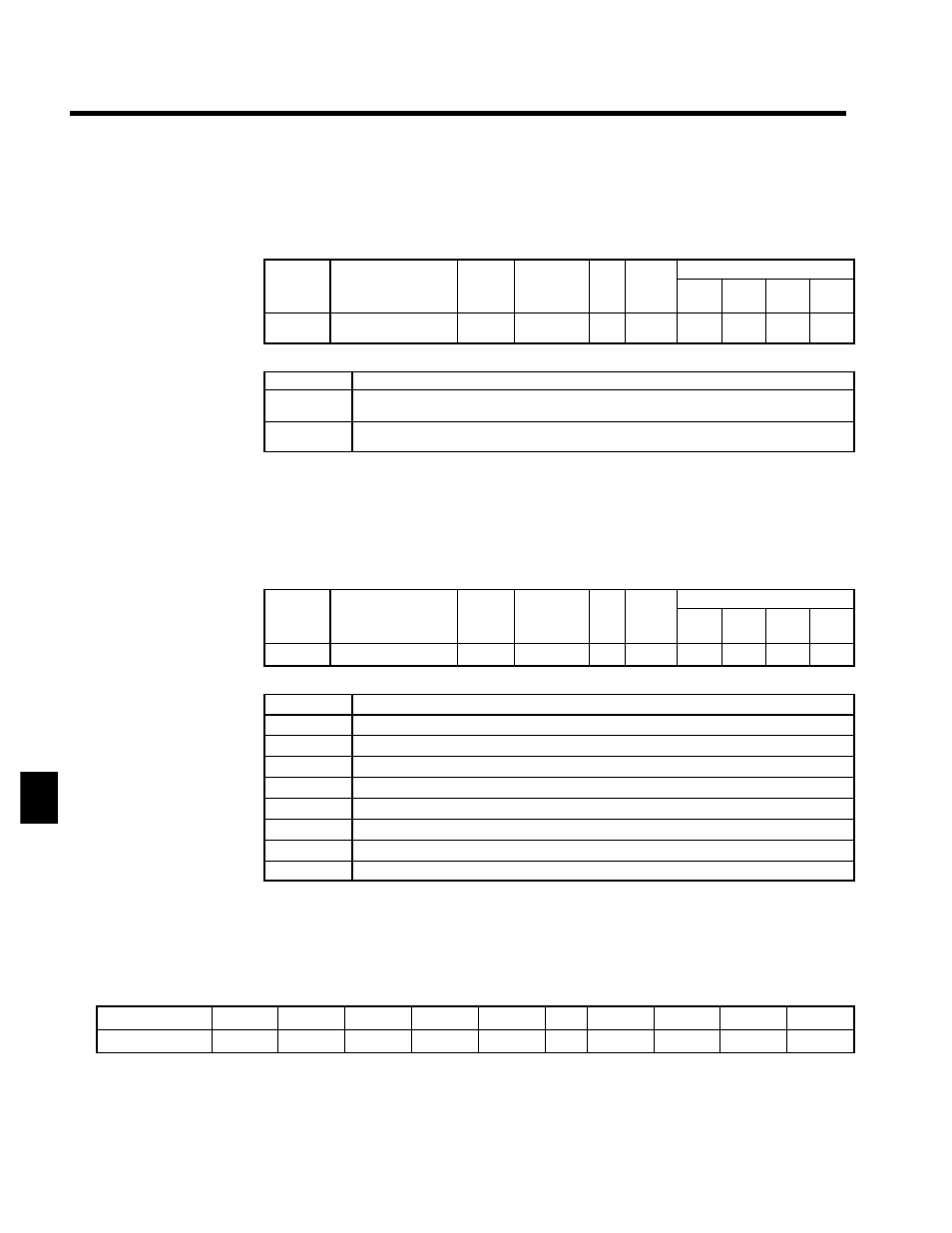
Analog Reference Card: F2-01
D
When using a AI-14B/A1-14U Analog Reference Card, set constant b1-01 (reference selection) to “3”
(option).
D
When using a AI-14B, set the function for channels 1 to 3 with constant F2-01. (There are no constants
to set for AI-14U.)
User
Change
during
Setting
Factory
Valid Access Levels
User
Constant
Number
Name
g
during
Opera-
tion
Setting
Range
Unit Factory
Setting
V/f
Control
V/f with
PG
Open
Loop
Vector
Flux
Vector
F2-01
Bi-polar or uni-polar
input selection
x
0, 1
--
0
B
B
B
B
D
Settings
Setting
Description
0
3-channel individual input (CH1: terminal 36; CH2: terminal 39; CH3:
terminal 42)
(b1-01 = 1)
1
3-channel additional input (Sum of CH1 to CH3 is used as the frequency
reference value.)
(b1-01 = 3)
D
Constant b1-01 (reference selection) must be set to “1” (external terminal), when 3-channel individual
input (setting: 0) is set.
D
When using a AI-14B and setting 3-channel individual input, the multi-function inputs cannot be set
to the Option/Inverter selection function (setting: 2).
J
Digital Reference Card: F3-01
D
When using a DI-08 or DI-16H2 Digital Reference Card, set constant b1-01 (reference selection) to “3”
(option) and set the input method with constant F3-01.
User
Change
during
Setting
Factory
Valid Access Levels
User
Constant
Number
Name
g
during
Opera-
tion
Setting
Range
Unit Factory
Setting
V/f
Control
V/f with
PG
Open
Loop
Vector
Flux
Vector
F3-01
Digital input option
x
0 to 7
--
0
B
B
B
B
D
Settings
Setting
Description
0
BCD 1% unit
1
BCD 0.1% unit
2
BCD 0.01% unit
3
BCD 1 Hz unit
4
BCD 0.1 Hz unit
5
BCD 0.01 Hz unit
6
BCD special setting (5-digit input) (Only when DI-16H2 is used.)
7
Binary input (Setting is displayed in decimal notation.)
D
The maximum frequency (100% speed) reference will be used when the binary input is set (setting: 7)
and all bits are “1.”
•
DI-08:
Maximum output frequency reference (255/100%).
•
DI-16H2: Maximum output frequency reference (16 bits: 30000/100%, 12 bits: 4095/100%).
D
Setting 6, BCD special setting (5-digit input), is valid only when the D1-16H2 is used. Using this setting,
a frequency from 0.00 to 399.98 Hz can be set in BCD. The data input method is different from that for
settings of 1 to 5.
Setting: 1 to 5
Sign
8
x
10
3
4
x
10
3
2
x
10
3
1
x
10
3
...
8
x
10
0
4
x
10
0
2
x
10
0
1
x
10
0
Setting: 6
2
x
10
4
1
x
10
4
8
x
10
3
4
x
10
3
2
x
10
3
...
1
x
10
1
8
x
10
0
4
x
10
0
2
x
10
0
D
The sign bit is used as a data bit, so only positive (plus) data can be set.
D
The second digit below the decimal point is set by bits 8x10
0
, 4x10
0
, and 2x10
0
, so the settings are made
in units of 0.02 Hz. (If these three bits are “111,” “110,” and “101,” they will be recognized as “9.”)
7