Yaskawa G5HHP Drive User Manual
Page 217
7.5 Common Functions
7 - 53
J
Carrier Frequency: C6-01 to C6-03
D
The carrier frequency characteristics differ according to the control method.
•
V/f control and V/f with PG feedback control: Carrier frequency variable setting possible.
•
Open-loop vector control and flux vector control: Constant frequency (The carrier frequency upper
limit only is set.)
D
The carrier frequency does not normally need to be adjusted.
User
Change
during
Setting
Factory
Valid Access Levels
User
Constant
Number
Name
g
during
Opera-
tion
Setting
Range
Unit Factory
Setting
V/f
Control
V/f with
PG
Open
Loop
Vector
Flux
Vector
C6-01
Carrier frequency up-
per limit
x
2.0
kHz
2.0
*
B
B
B
B
C6-02
Carrier frequency
lower limit
x
0.4 to 2.0
kHz
2.0
*
A
A
x
x
C6-03
Carrier frequency pro-
portional gain
x
00 to 99
Mul-
tiple
00
A
A
x
x
* The setting range and the factory setting vary according to the Inverter capacity. The table
shows a value of 400-V class, 200 kW. (See page 8 - 42.)
D
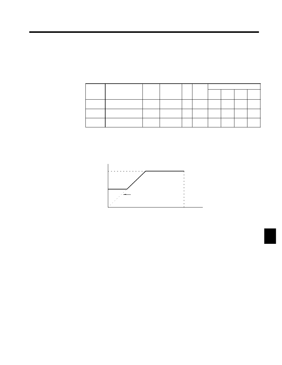
In the vector control modes, the carrier frequency is determined by the carrier frequency upper limit
(constant C6-01). In the V/f control modes (both with and without PG), the carrier frequency can be
changed in response to the output frequency by setting the carrier frequency lower limit (constant
C6-02) and the carrier frequency proportional gain (constant C6-03).
Carrier frequency
C6-01
C6-02
0
Output frequency
x (C6-03) x K
E1-04
(Maximum output frequency)
Output frequency
The coefficient “K” varies depending
on the carrier frequency upper limit, as
described below:
D
C6-01 ≧ 10.0kHz : K = 3
D
10.0kHz > C6-01 ≧ 5.0kHz : K = 2
D
5.0kHz > C6-01 : K = 1
Fig 7.26
Setting the Carrier Frequency
D
To make the carrier frequency constant, either set the same value for constants C6-01 and C6-02 or set
the carrier frequency proportional gain (constant C6-03) to “0” (i.e., fix at upper limit value). The fol-
lowing settings will generate a constant setting fault (OPE11):
•
Carrier frequency upper limit (C6-01) > 5.0 kHz and carrier frequency lower limit (C6-02) ≦ 5.0 kHz
•
Carrier frequency proportional gain (C6-03) > 6 and (C6-01) < C6-02)
D
If the lower limit is set higher than the upper limit, the lower limit will be disregarded and carrier frequency will be
fixed at the upper limit.
7