Pg pulse output monitor division rate: f1-06 – Yaskawa G5HHP Drive User Manual
Page 145
6.4 Flux Vector Control
6 - 27
VS-616G5
Motor
PG (encoder)
Forward
Pulse output
Phase A
Phase B
Phase A
Phase B
[Setting: 0]
[Setting: 1]
D
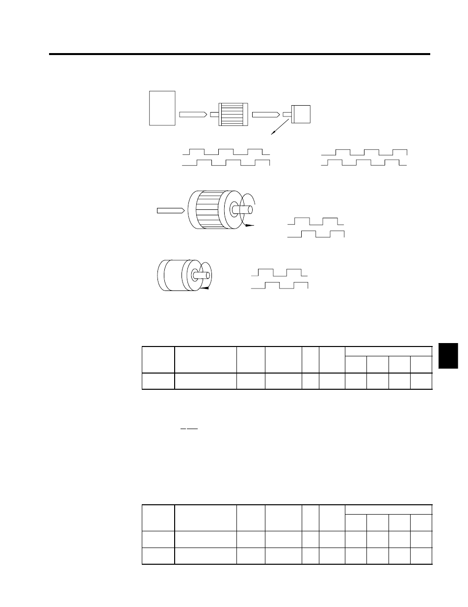
Forward rotation in a typical motor (applicable Yaskawa PG: made by Thermtac):
Forward
The motor output shaft rotates in
the counterclockwise direction
with a forward inverter reference.
Phase A
Phase B
Forward rotation
D
Phase A leading in a typical PG:
Phase A leads when the input axis rotates clockwise.
Phase A
Phase B
Fig 6.12
PG Rotation Direction Setting
J
PG Pulse Output Monitor Division Rate: F1-06
D
This constant is effective only when a PG-B2 PG Control Card is used.
D
It sets the division ratio used when the pulse monitor output is connected to a pulse input device.
User
Change
during
Setting
Factory
Valid Access Levels
User
Constant
Number
Name
g
during
Opera-
tion
Setting
Range
Unit Factory
Setting
V/f
Control
V/f with
PG
Open
Loop
Vector
Flux
Vector
F1-06
PG division rate (PG
pulse monitor)
x
1 to 132
--
1
x
B
x
B
D
The first digit in the setting (0 or 1) is n and the second two digits (01 to 32) are m. The division ratio
is calculated from n and m with the following equation:
Division ratio = ( 1+n )/m
Setting Ranges
n: 0, 1
m: 1 to 32
F1-06 =
m
n
D
Possible division rate settings are as follows: 1/32 ≦ F1-06 ≦ 1. For example, if the division rate is 1/2
(a setting of “2”), the monitor output will be half of the number of pulses output from the PG.
J
Fault Detection Functions: F1-02 to F1-04, F1-08 to F1-11, F1-14
PG Disconnection Stopping Method: F1-02, F1-14
D
Sets the PG open-circuit detection time and stopping method that is used when a break is detected in
the PG cable (PGO).
User
Change
during
Setting
Factory
Valid Access Levels
User
Constant
Number
Name
g
during
Opera-
tion
Setting
Range
Unit Factory
Setting
V/f
Control
V/f with
PG
Open
Loop
Vector
Flux
Vector
F1-02
Operation selection at
PG open circuit
x
0 to 3
--
1
x
B
x
B
F1-14
PG open-circuit detec-
tion time
x
0.0 to 10.0
s
2.0
x
A
x
A
6