Yaskawa G5HHP Drive User Manual
Page 85
4.2 Modes
4 - 17
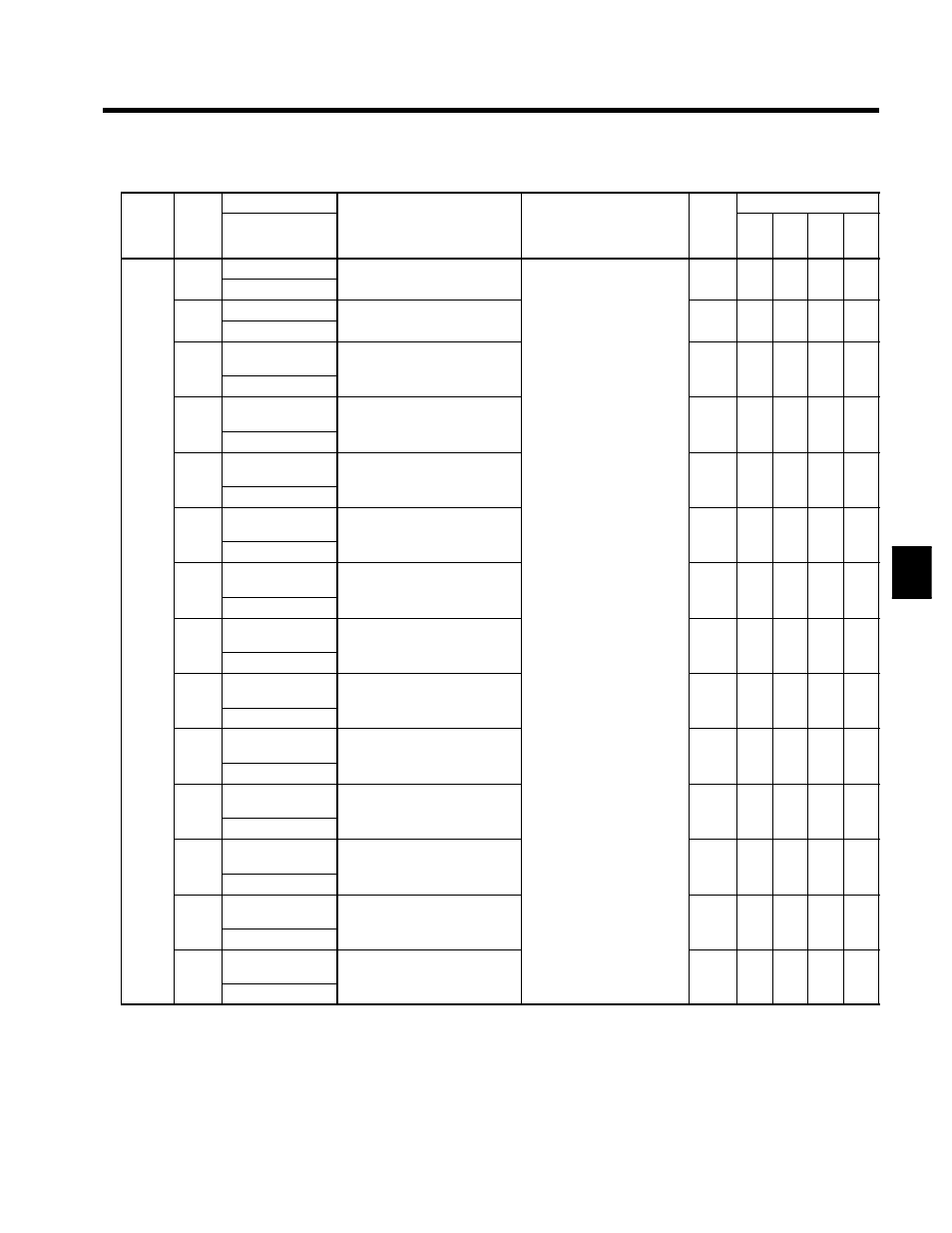
Table 4.3 Constants Monitored in Operation Mode (Continued)
Const
Name
Output Signal Levels for
Valid Access Levels
Func-
tion
Const
ant
No.
Digital Operator
Display
Function
Output Signal Levels for
Multi-function Analog Out-
puts
Min.
Units
V/f
V/f w/
PG
Open
-loop
Vec-
tor
Flux
Vec-
tor
U2-01
Current fault
Information on the current fault
Q
Q
Q
Q
U2-01
Current Fault
Information on the current fault
--
Q
Q
Q
Q
U2-02
Last fault
Information on the last fault
Q
Q
Q
Q
U2-02
Last Fault
Information on the last fault
--
Q
Q
Q
Q
U2-03
Frequency refer-
ence at fault
Frequency reference value when
the “last fault” occurred
0.01
Hz
Q
Q
Q
Q
U2 03
Frequency Ref
the “last fault” occurred.
Hz
Q
Q
Q
Q
U2-04
Output frequency
at fault
Output frequency when the “last
fault” occurred
0.01
Hz
Q
Q
Q
Q
U2 04
Output Freq
fault” occurred.
Hz
Q
Q
Q
Q
U2-05
Output current at
fault
Output current when the “last
fault” occurred
0.1 A
Q
Q
Q
Q
U2 05
Output Current
fault” occurred.
0.1 A
Q
Q
Q
Q
U2-06
Motor speed at
fault
Motor speed when the “last fault”
occurred
0.01
Hz
X
Q
Q
Q
U2 06
Motor Speed
occurred.
Hz
X
Q
Q
Q
U2-07
Output voltage ref-
erence at fault
Output voltage when the “last
fault” occurred
0.1 V
Q
Q
Q
Q
Fault
U2 07
Output Voltage
fault” occurred.
0.1 V
Q
Q
Q
Q
Fault
trace
(See
note )
U2-08
DC bus voltage at
fault
The main circuit DC voltage
when the “last fault” occurred
Can’t be output.
1 V
Q
Q
Q
Q
note.)
U2 08
DC Bus Voltage
when the “last fault” occurred.
1 V
Q
Q
Q
Q
U2-09
Output power at
fault
Output power when the “last
fault” occurred
0.1 kW
Q
Q
Q
Q
U2 09
Output kWatts
fault” occurred.
0.1 kW
Q
Q
Q
Q
U2-10
Torque reference
at fault
Torque reference when the “last
fault” occurred.
0.1 %
X
X
Q
Q
U2 10
Torque Reference
au t occu ed.
(The rated torque = 100%.)
0.1 %
X
X
Q
Q
U2-11
Input terminal sta-
tus at fault
Input terminal status when the
“last fault” occurred.
--
Q
Q
Q
Q
U2 11
Input Term Sts
ast au t occu ed.
(Same format as U1-10.)
--
Q
Q
Q
Q
U2-12
Output terminal
status at fault
Output terminal status when the
“last fault” occurred.
--
Q
Q
Q
Q
U2 12
Output Term Sts
last fault occurred.
(Same format as U1-11.)
--
Q
Q
Q
Q
U2-13
Operation status
at fault
Inverter operating status when the
“last fault” occurred.
--
Q
Q
Q
Q
U2 13
Inverter status
last fault occurred.
(Same format as U1-12.)
--
Q
Q
Q
Q
U2-14
Cumulative opera-
tion time at fault
Elapsed operating or power-on
time when the “last fault” oc-
1 hr
Q
Q
Q
Q
U2 14
Elapsed time
time when the last fault oc
curred.
1 hr
Q
Q
Q
Q
Note When faults CPF00, 01, 02, 03, UV1 and UV2 occur, a fault trace is not performed.
4