7 selecting the stopping method: b1-03 – Yaskawa G5HHP Drive User Manual
Page 130
Basic Operation
6.1.7 Selecting the Stopping Method: b1-03
6 - 12
6.1.7 Selecting the Stopping Method: b1-03
D
Set the stopping method used when a stop command is input.
User
Change
during
Setting
Factory
Valid Access Levels
User
Constant
Number
Name
g
during
Opera-
tion
Setting
Range
Unit Factory
Setting
V/f
Control
V/f with
PG
Open
Loop
Vector
Flux
Vector
b1-03
Stopping method
selection
x
0 to 3
--
0
Q
Q
Q
Q
D
Only settings 0 and 1 can be used with flux vector control.
D
Settings
Setting
Function
0
Deceleration to stop
1
Coast to stop
2
DC braking stop: Stops faster than coast to stop, without regenerative operation.
3
Coast to stop with timer: Run commands are disregarded during deceleration time.
D
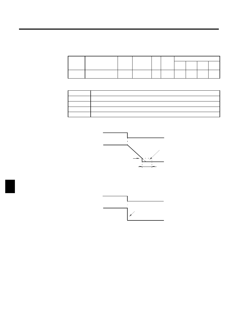
The following diagrams show the operation of each stopping method.
•
Deceleration to Stop (b1-03 = 0)
Run command
ON
OFF
Output frequency
Deceleration
time
DC injection braking
Excitation level (b2-01)
DC injection braking time at stop (b2-04)
Decelerates to a stop at a rate set with the selected deceleration time.
Fig 6.4
Deceleration to Stop
•
Coast to Stop (b1-03 = 1)
Run command
ON
OFF
Output frequency
The inverter output is shut OFF when the stop command
is input and the run command goes OFF.
After the stop command is input, run commands are disregarded
until the minimum baseblock time (L2-03) has elapsed.
Fig 6.5
Coast to Stop
•
DC Injection Braking Stop (b1-03 = 2)
6