Pg-b2 (for flux vector control mode only), Fig 3.12 pg-b2 wiring i/o circuit configuration, Fig 3.13 i/o circuit configuration of the pg-b2 – Yaskawa G5HHP Drive User Manual
Page 59
3.7 Installing and Wiring PG Speed Control Cards
3 - 19
J
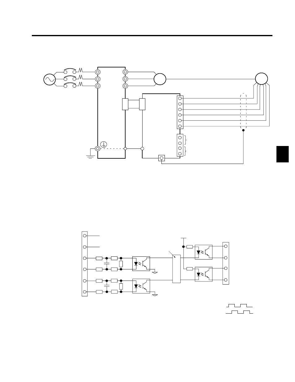
PG-B2 (For Flux Vector Control Mode Only)
PG
Power supply +12 V
Power supply 0 V
B-phase pulse monitor output
A-phase pulse monitor output
A-phase pulse output (+)
A-phase pulse output (--)
B-phase pulse output (+)
B-phase pulse output (--)
Three-phase, 400 VAC
(575 VAC)
VS-616G5
4CN
R/L1
S/L2
T/L3
U/T1
V/T2
W/T3
IM
PG-B2
4CN
TA1
E
TA3 (E)
1
2
3
4
5
6
TA2
1
2
3
4
D
Shielded twisted-pair wires must be used for signal lines.
D
Do not use the pulse generator’s power supply for anything other than the
pulse generator (encoder). Using it for another purpose can cause malfunctions
due to noise.
D
The length of the pulse generator’s wiring must not be more than 100 meters.
D
The direction of rotation of the PC can be set in user constant F1-05. The
factory preset if for forward rotation, A-phase advancement.
E
Fig 3.12
PG-B2 Wiring
I/O Circuit Configuration
TA1
PG power
supply +12 V
A-phase
pulse input
1
2
3
4
5
6
+12 V
0 V
B-phase
pulse input
150
180
150
180
470
A-phase
pulses
B-phase
pulses
150
180
150
180
470
Division rate circuit
1
2
3
4
A-phase pulse monitor
output
B-phase pulse monitor
output
A-phase
pulses
B-phase
pulses
D
When connecting to a voltage-output-type PG (encoder), select a PG
that has an output impedance with a current of at least 12 mA to the
input circuit photocoupler (diode).
TA2
Fig 3.13
I/O Circuit Configuration of the PG-B2
3