2 zero-servo function – Yaskawa G5HHP Drive User Manual
Page 182
Advanced Operation
7.3.2 Zero-servo Function
7 - 18
Torque
100%
0
Reference
speed
Speed
b7-01
Droop amount (Slip equivalent)
Fig 7.6
Droop Control Gain
7.3.2 Zero-servo Function
The zero-servo function is enabled when one of the multi-function inputs (H1-01 to H1-06) is set to 72 (zero
servo command). If the zero servo command is ON when the frequency (speed) reference falls below the
zero speed level (b2-01), a position control loop is formed and the motor is stopped. (The motor will not
rotate even if there is an offset in the analog command input.)
J
Zero-servo Settings: b9-01, b9-02
User
Change
during
Setting
Factory
Valid Access Levels
User
Constant
Number
Name
g
during
Opera-
tion
Setting
Range
Unit
Factory
Setting
V/f
Control
V/f with
PG
Open
Loop
Vector
Flux
Vector
b9-01
Zero-servo gain
x
0 to 100
--
5
x
x
x
A
b9-02
Zero-servo comple-
tion width
x
0 to 16383
Pulses
10
x
x
x
A
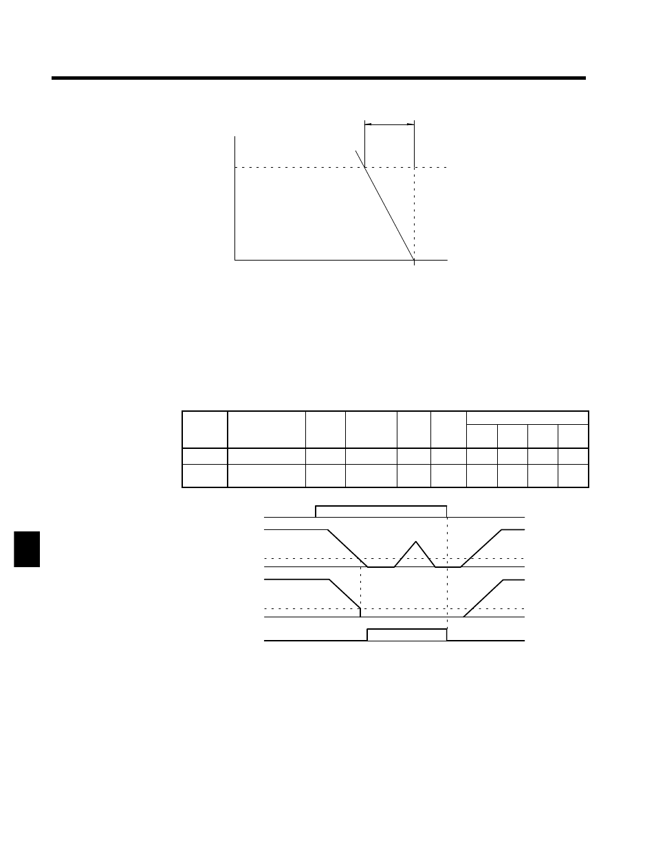
A time chart for the zero servo function is given in Figure 7.7.
Zero servo command
OFF
ON
Frequency (speed)
reference
Excitation level (b2-01)
Motor speed
Zero Servo End signal
Completely stopped by
zero-servo function
Excitation level (b2-01)
Fig 7.7
Time Chart for Zero Servo
D
Assign the zero servo command (setting 72) to one of the multi-function inputs (H1-01 to H1-06).
D
The zero-servo status is entered when the frequency (speed) reference falls below the zero-speed level
(b2-01).
D
Be sure to leave the run command input ON. If the run command is turned OFF, the output will be inter-
rupted and the zero-servo function will become ineffective.
D
Adjust the holding strength of the zero-servo with constant b9-01 (Zero Servo Gain). Increasing this
setting increases the holding strength, although oscillation will occur if the setting is too high. (Adjust
the holding strength after adjusting the speed control (ASR) gain.)
7