1 application constants: b – Yaskawa G5HHP Drive User Manual
Page 205
7.5 Common Functions
7 - 41
7.5.1 Application Constants: b
J
DC Injection Braking: b2-01 to b2-04
D
The DC injection braking function decelerates by applying a DC current to the motor. This happens in
the following two cases
•
DC Injection Braking Time at Start:
Effective for temporarily stopping and then restarting, without regenerative processing, a motor
coasting by inertia.
•
DC Injection Braking Time at Stop:
Used to prevent coasting by inertia when the motor is not completely stopped by normal decelera-
tion when there is a large load. The stopping time can be shortened by lengthening the DC injection
braking time or increasing the DC injection braking current.
User
Change
during
Setting
Factory
Valid Access Levels
User
Constant
Number
Name
g
during
Opera-
tion
Setting
Range
Unit Factory
Setting
V/f
Control
V/f with
PG
Open
Loop
Vector
Flux
Vector
b2-01
Zero speed level (DC
injection braking
starting frequency)
x
0.0 to 10.0
Hz
0.5
B
B
B
B
b2-02
DC injection braking
current
x
0 to 100
%
50
B
B
B
x
b2-03
DC injection braking
time at start
x
0.00 to
10.00
s
0.00
B
B
B
B
b2-04
DC injection braking
time at stop
x
0.00 to
10.00
s
0.50
B
B
B
B
D
For the zero speed level (b2-01), set the frequency for beginning DC injection braking for deceleration.
If the excitation level is lower than the minimum output frequency (E1-09), the DC injection braking
will begin from the minimum output frequency.
D
In flux vector control mode, DC injection braking becomes the initial excitation starting frequency at
the time of deceleration. In that case, braking starts from the excitation level regardless of the minimum
output frequency setting.
D
The excitation level is also used as the operating frequency for the zero servo function (for flux vector
control only).
D
For the DC injection braking current (b2-02), set the value for the current that is output at the time of
DC injection braking. DC injection braking current is set as a percentage of Inverter rated output current,
with the Inverter rated output current taken as 100%.
D
For the DC injection braking time at start (b2-03), set the DC injection braking operating time for when
the motor is started.
D
For the DC injection braking time at stop (b2-04), set the DC injection braking operating time for when
the motor is stopped.
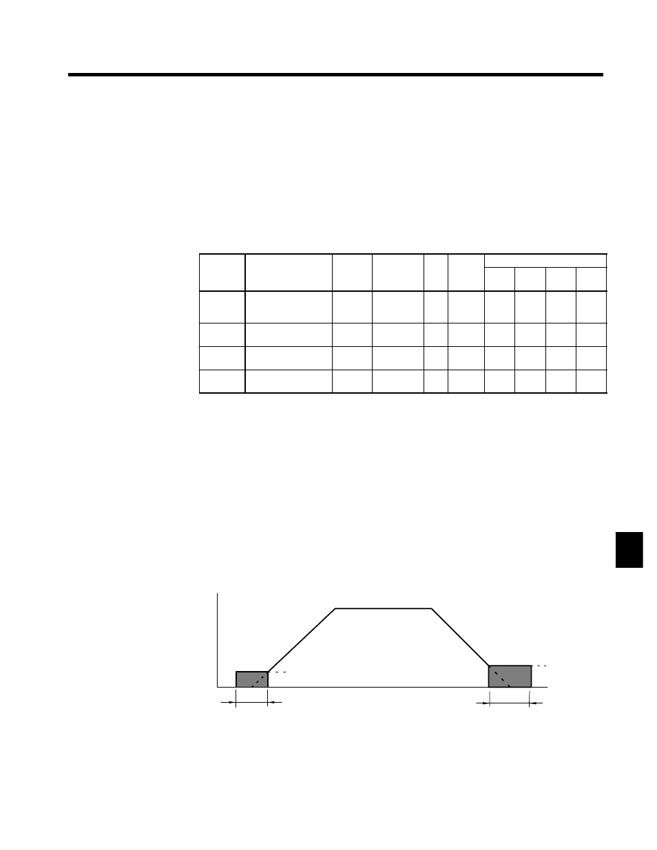
D
Figure 7.18 provides a timing chart of DC injection braking (initial excitation).
Output frequency
E1-09
(Min. output frequency)
b2-03
(DC injection braking time at start)
The larger of
b2-01 or
E1-09
b2-04
(DC injection braking
time at stop)
Time
Fig 7.18
DC Injection Braking Timing Chart
7