5 v/f control with pg, 1 motor constants: e1-01, e1-02, e2-01, e2-04, Inverter input voltage setting: e1-01 – Yaskawa G5HHP Drive User Manual
Page 157
6.5 V/f Control with PG
6 - 39
6.5 V/f Control with PG
With V/f control with a PG, the user must set the motor constants, V/f pattern, and PG Control Card settings, and
then adjust the speed control gain.
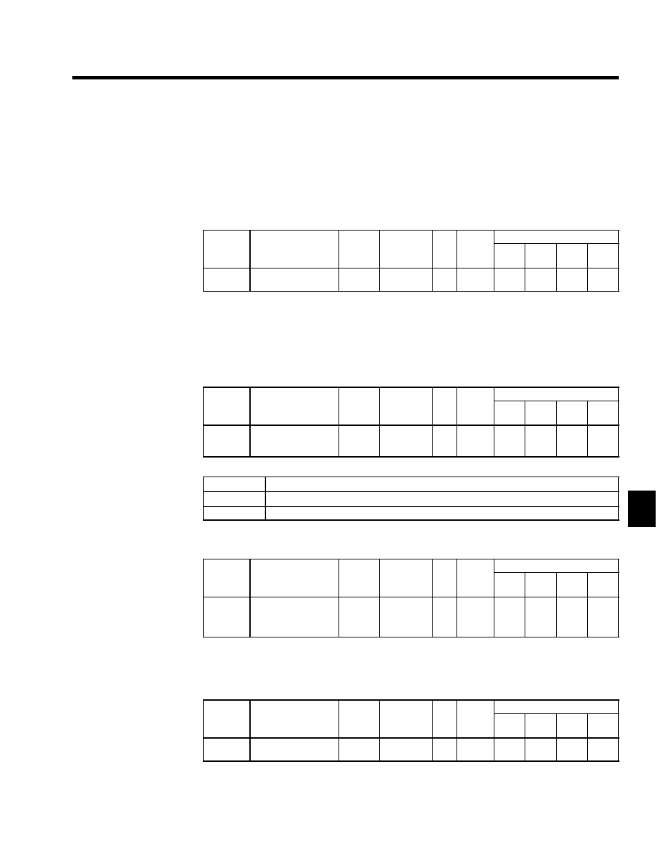
6.5.1 Motor Constants: E1-01, E1-02, E2-01, E2-04
J
Inverter Input Voltage Setting: E1-01
D
Set the Inverter’s input voltage to match the power supply voltage.
User
Change
during
Setting
Factory
Valid Access Levels
User
Constant
Number
Name
g
during
Opera-
tion
Setting
Range
Unit Factory
Setting
V/f
Control
V/f with
PG
Open
Loop
Vector
Flux
Vector
E1-01
Input voltage setting
x
360 to 460
(460 to 690)
VA
C
400
(600)
Q
Q
Q
Q
D
The voltage settings shown in parentheses are for the 575-V class Inverters.
D
This setting is used as the reference value for functions such as the protection functions.
J
Motor Selection: E1-02, E2-01, E2-04
Motor Selection (Motor Overheating Protection): E1-02
D
Set the type of motor being used with the motor selection constant (E1-02). This setting is a reference
for overheating protection functions.
User
Change
during
Setting
Factory
Valid Access Levels
User
Constant
Number
Name
g
during
Opera-
tion
Setting
Range
Unit Factory
Setting
V/f
Control
V/f with
PG
Open
Loop
Vector
Flux
Vector
E1-02
Motor selection (mo-
tor overheating
protection)
x
0, 1
--
0
Q
Q
Q
Q
D
Settings
Setting
Function
0
Standard motor (general-purpose motor)
1
Special motor (inverter-exclusive motor)
Motor Rated Current (Electronic Thermal Reference Current): E2-01
D
Set the rated current (A) shown on the motor nameplate.
User
Change
during
Setting
Factory
Valid Access Levels
User
Constant
Number
Name
g
during
Opera-
tion
Setting
Range
Unit Factory
Setting
V/f
Control
V/f with
PG
Open
Loop
Vector
Flux
Vector
E2-01
Motor rated current
(electronic thermal
reference current)
x
10% to
200%
(of rated
current)
*1
A
*2
Q
Q
Q
Q
* 1. The setting range is 10% to 200% of the Inverter rated output current.
* 2. The factory setting depends upon the type of Inverter. Refer to pages 8 - 42.
Number of Motor of Poles: E2-04
D
Set constant (E2-04) to the number of poles shown on the motor nameplate.
User
Change
during
Setting
Factory
Valid Access Levels
User
Constant
Number
Name
g
during
Opera-
tion
Setting
Range
Unit Factory
Setting
V/f
Control
V/f with
PG
Open
Loop
Vector
Flux
Vector
E2-04
Number of motor
poles
x
2 to 48
--
4
x
Q
x
Q
6